Broadband multi-waveguide output device for rotary traveling wave tube

A technology for output devices and tubes, applied in the direction of the coupling device of the transit time type electron tube, etc., can solve the problems of narrow bandwidth of the resonant structure, narrow bandwidth, and the inability to use broadband gyrotraveling wave tubes, etc., to achieve high gain and overcome the narrow bandwidth , the effect of compact structure

Active Publication Date: 2012-06-20
UNIV OF ELECTRONICS SCI & TECH OF CHINA
View PDF4 Cites 15 Cited by
  • Summary
  • Abstract
  • Description
  • Claims
  • Application Information

AI Technical Summary

Problems solved by technology

However, the current quasi-optical output device has a relatively narrow bandwidth, which is only suitable for a cyclotron oscillator working at a single frequency point, but not for a broadband cyclotron traveling wave tube.
The horizontal output device disclosed in the patent document with the publication number CN101562268A and the title of invention "A Multi-Waveguide Output Structure for Convoluted Amplifier" includes an inner cylindrical cavity and an outer circular ring with a coaxial center. Cavity, the inner and outer cavities are separated by an annular common wall to form a compound cavity, and a plurality of rectangular coupling holes are arranged at annular intervals on the common wall, and the housing of the outer ring cavity facing the coupling holes is also separately An output waveguide is provided, and two small and large cylindrical waveguides are respectively arranged on the upper and lower end faces of the inner cylindrical cavity around the axis; The resonance between the outer ring cavities couples the electromagnetic wave from the axial transmission direction to the transverse waveguide to avoid the re-acceleration of the electron beam by the electromagnetic wave, but due to the limitation of its resonance structure, the bandwidth of this coupling method is very narrow , so it cannot be used in conjunction with the broadband gyrotraveling wave tube

Method used


Image

  • Broadband multi-waveguide output device for rotary traveling wave tube
  • Broadband multi-waveguide output device for rotary traveling wave tube
  • Broadband multi-waveguide output device for rotary traveling wave tube

Examples


Embodiment Construction

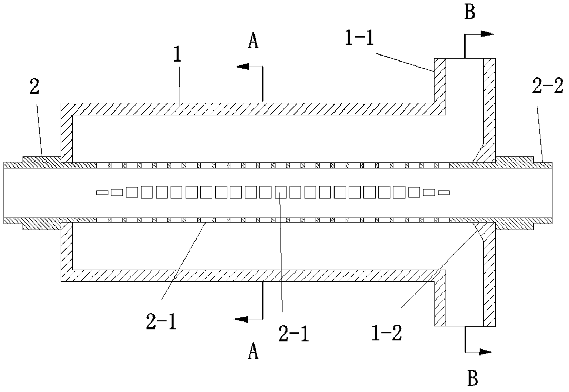
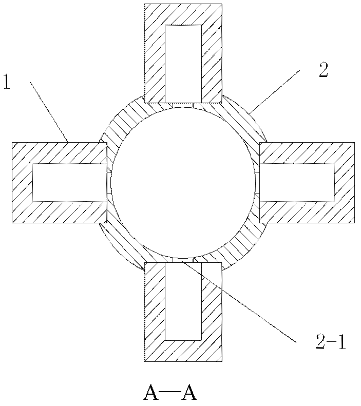
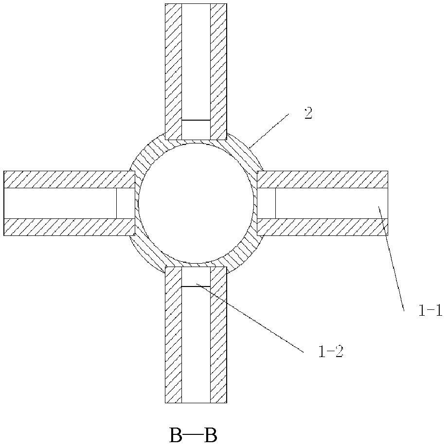
[0023] The following is based on the input center frequency of 30GHz (center frequency wavelength is 8mm), TE 21 Mode (i.e. m=2) is an example of a multi-waveguide output device for the large-convolution second-harmonic gyrotron traveling-wave tube, with figure 1 That is the structural diagram of the output device, the entire output device is made of oxygen-free copper; where:

[0024] The circular waveguide 2 has a diameter of Ф14.2mm and a length of 210mm. There are four sets of rectangular coupling holes along the axial direction on it. Each coupling hole group 2-1 has 24 rectangular coupling holes respectively. Each rectangular coupling hole group 2- 1 Set at intervals of 90°, the width a of the first rectangle at both ends of each coupling hole group 2-1 1 This embodiment is all 0.95mm, the width of the 2nd, 3rd, 4th hole is in a 1 On the basis of , its width coefficient is respectively determined by the 2nd, 3rd, and 4th items of the Chebyshev polynomial. In the presen...


PUM


Abstract

The invention belongs to a broadband multi-waveguide output device for a rotary traveling wave tube. The broadband multi-waveguide output device comprises a circular waveguide, long stripped rectangular waveguides and rectangular coupling holes, wherein the circular waveguide is provided with an input opening and an output opening, the long stripped rectangular waveguides are arranged on a circular waveguide casing at intervals in the axial direction and are provided with microwave output openings, the rectangular coupling holes are arranged between the circular waveguide and the rectangular waveguides, the axial lengths of all holes are identical, the center distances among all holes are identical, the widths of four front holes at two ends of each group of rectangular holes are in step-type arrangement from narrow to wide, the width of each hole in the middle is the same as the width of the fourth hole at the two ends, and in addition, an inclined coupling surface is also arranged at the junction part of each rectangular waveguide inner cavity front end surface and the circular waveguide. The multi-waveguide output device has the characteristics that the requirements of the millimeter band of high power, high gain and high frequency band for being matched with the rotary traveling wave tube to be used can be sufficiently met, the base parameters are provided for the optimization design of voltage reduction collection electrodes, and the like. The defects of narrow band width, matching use difficulty with the broadband rotary traveling wave tube, and the like in the prior art are overcome.

Description

technical field [0001] The invention relates to a microwave output device in a vacuum component, in particular to a broadband multi-waveguide output device for a cyclotron traveling wave tube with broadband lateral output. Background technique [0002] Traditional microwave tubes such as magnetrons, traveling wave tubes, and return wave tubes will encounter serious difficulties when extending to the millimeter wave band, and the power output will drop sharply. Therefore, seeking millimeter-wave and submillimeter-wave devices based on new principles has always been the goal of people's efforts, resulting in a series of new devices that are different from traditional microwave tubes, such as gyrotrons. Because the gyrotron traveling wave tube in the gyrotron has excellent performance of high power, high gain and wide frequency band in the millimeter wave band, it has been developed rapidly. [0003] In order to improve the output power and bandwidth of the gyro TWT, a series ...

Claims


Application Information

Patent Timeline
Patent Type & Authority Applications(China)
IPC IPC(8): H01J23/36
Inventor 王建勋罗勇陈宪龙刘国王丽徐勇鄢然
Owner UNIV OF ELECTRONICS SCI & TECH OF CHINA
Why Eureka
Try Eureka