Compression bar type passive low-frequency three-dimensional vibration isolator

A compression rod type and vibration isolator technology, which is applied in the direction of shock absorbers, shock absorber-spring combinations, shock absorbers, etc., can solve problems such as vibration isolation, and achieve high stability

Inactive Publication Date: 2013-09-11
UNIV OF SCI & TECH OF CHINA
View PDF5 Cites 0 Cited by
  • Summary
  • Abstract
  • Description
  • Claims
  • Application Information

AI Technical Summary

Problems solved by technology

[0004] In order to solve the problem of vibration isolation in low-frequency environments, the present invention provides a pressure rod-type passive low-frequency three-way vibration isolator suitable for vibration isolation in low-frequency environments

Method used


Image

  • Compression bar type passive low-frequency three-dimensional vibration isolator
  • Compression bar type passive low-frequency three-dimensional vibration isolator
  • Compression bar type passive low-frequency three-dimensional vibration isolator

Examples


Embodiment 1

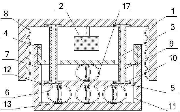
[0027] see figure 1 , the bar-type passive low-frequency three-way vibration isolator includes a barrel-shaped base 7, and more than three lower elastic elements 6 are evenly installed in the base 7 through splints 13, and the lower elastic elements 6 are wire rope springs. The diameter, number of strands, length, number of turns, winding method and degree of tightness are used to design the required bearing capacity, stiffness and damping in the vertical direction. An annular step is provided on the side wall of the opening end of the upper part of the base 7, and four guide grooves 11 along the axial direction are evenly distributed on the inner wall of the base 7 at the lower part of the annular step, see Figure 4 ; The top of the lower elastic element 6 is provided with a circular support platform 5, and four guide blocks 12 are evenly distributed on the circumference of the support platform 5, see Figure 5 , the four guide blocks 12 and the four guide grooves 11 are co...

Embodiment 2

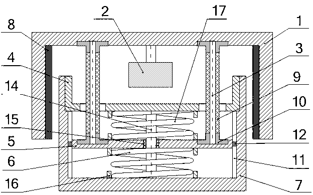
[0031] see figure 2 , and the main difference of embodiment 1 is that: support platform 5 middle part is provided with through hole, and center guide rod 14 passes through the through hole of support platform 5 and is connected with upper baffle plate 4 at the upper end, and the lower end is connected with base 7; support platform 5 and upper The upper elastic element 17 is set on the center guide rod 14 between the baffle plates 4, and the lower elastic element 6 is set on the center guide rod 14 between the support table 5 and the base 7, and the upper elastic element 17 and the lower elastic element 6 are both coil spring. Limiting ring 16 is respectively installed on the top surface of the support table 5 corresponding to the upper end and the lower end of the upper elastic element 17 and the bottom surface of the upper baffle plate 4; Limiting rings 16 are respectively installed on the bottom surface of the base 7 . The annular elastic element 8 is made of rubber. Oth...

Embodiment 3

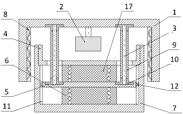
[0033] see image 3, and the main difference of embodiment 3 is: the material of the lower elastic element 6 and the upper elastic element 17 are both rubber-metal composite springs; the material of the annular elastic element 8 is rubber-steel rope composite spring. Others are with embodiment 2. Mainly on the basis of embodiment 2, the damping and bearing capacity of the vibration isolator are increased, and it is mainly used in a vibration isolation system where low-frequency vibration isolation requirements are not too strict.


PUM


Abstract

The invention relates to a compression bar type passive low-frequency three-dimensional vibration isolator. Lower elastic elements, a circular support table, upper elastic elements and a disc-shaped upper baffle are arranged in a base of the vibration isolator in turn; low ends of more than three elastic compression bars correspondingly penetrate through more than three round holes on the upper baffle respectively and are connected to the support table, and the upper ends of the more than three elastic compression bars are respectively connected with a circular cover-shaped bearing shell; rubber damping sleeves are sleeved on the more than three compression bars; the bearing shell covers the base; the inner side wall of the bearing shell is provided with annular elastic elements; the top on the inner side of the bearing shell is provided with a damping cylinder; and the damping cylinder is filled with a liquid damping material. The compression bar type passive low-frequency three-dimensional vibration isolator has an ultralow-frequency vibration isolating and impact resisting capacity in the vertical and horizontal directions, can be widely applied to vibration isolating precision machining and vibration control of measurement instruments, is a passive shock absorber, and can realize a low-frequency vibration isolating and impact resisting function without extra energy.

Description

technical field [0001] The invention belongs to the technical field of vibration reduction of precision instruments, and in particular relates to a low-frequency vibration isolator used for precision machining and measurement in low-frequency environments. technical background [0002] With the rapid development of various precision engineering fields, ultra-precision machining and precision measurement technology put forward higher and higher requirements for its working environment. Small vibrations in the external environment will greatly reduce the processing accuracy of ultra-precision instruments, causing large errors in various precision measurements, and even making measurements impossible. Therefore, the vibration isolation performance of precision instruments directly affects its operating performance. The main indicators affecting the vibration isolation performance are the natural frequency and damping ratio of the vibration isolation system, in which the natural...

Claims


Application Information

Patent Timeline
Patent Type & Authority Patents(China)
IPC IPC(8): F16F13/02F16F15/02
Inventor 龚兴龙彭超郭朝阳宗路航严启凡周宏
Owner UNIV OF SCI & TECH OF CHINA
Why Eureka
Try Eureka