
Low energy consumption system for purifying and incinerating harmful gases

A waste gas purification and low energy consumption technology, which is applied in the direction of incinerators, combustion methods, combustion types, etc., can solve the problems of dusty and harmful waste gas blockage, incomplete combustion of harmful waste gas, and high energy consumption, so as to reduce energy consumption and reduce incineration Effect of Processing Fees

Inactive Publication Date: 2012-06-27
朱海生
View PDF1 Cites 8 Cited by
  • Summary
  • Abstract
  • Description
  • Claims
  • Application Information

AI Technical Summary

Problems solved by technology

[0011] Wood Invention's low-energy consumption harmful waste gas purification and incineration system adopts a number of the latest energy-saving combustion technologies and a number of energy-saving and consumption-reducing measures, and is optimized on the whole, which solves the excessive energy consumption of DTO (conventional chamber-type harmful waste gas incinerator) Large, RTO (Reversing Regenerative Hazardous Waste Gas Incinerator) does not burn all the harmful waste gas and the dust-containing harmful waste gas blocks the heat storage body, etc., and can continuously incinerate a variety of harmful waste gases at low cost

Method used


Image

  • Low energy consumption system for purifying and incinerating harmful gases
  • Low energy consumption system for purifying and incinerating harmful gases

Examples


Embodiment Construction

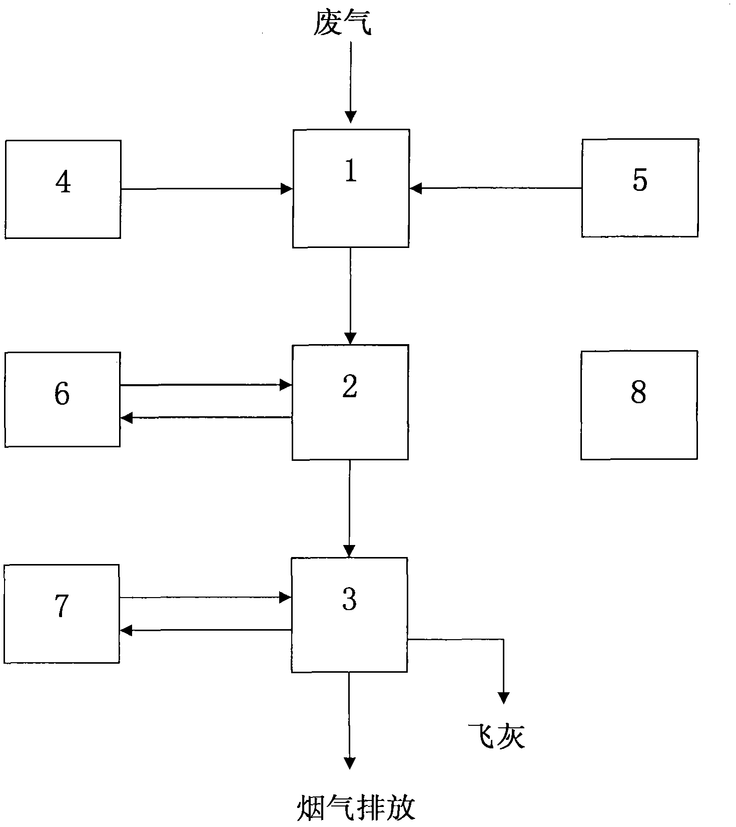
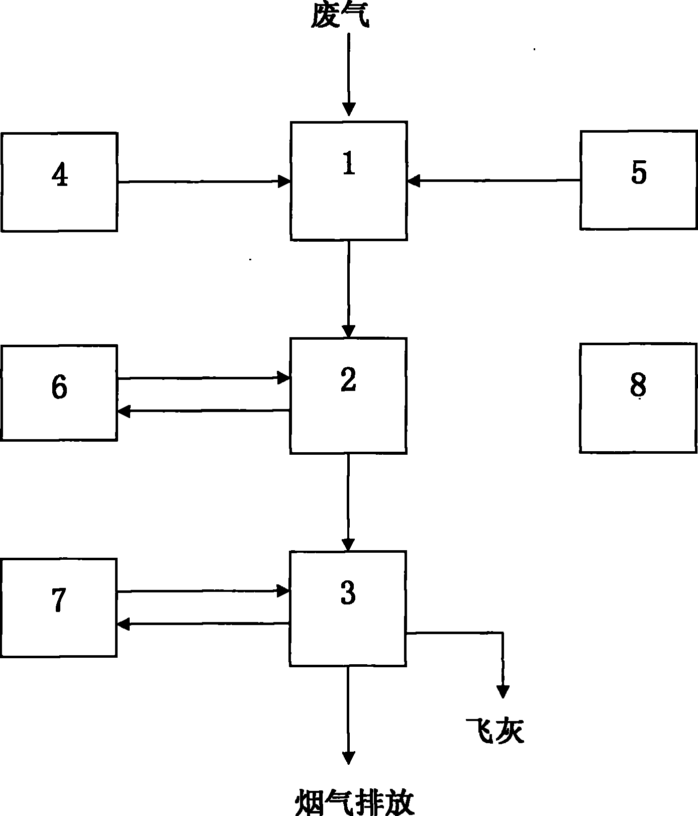
[0018] see figure 1 , low energy consumption harmful waste gas purification and incineration system, including: waste gas purification and incineration unit 1, waste heat recovery unit 2 and flue gas treatment unit 3 and other main equipment, as well as fuel supply equipment 4, combustion air supply equipment 5, heat exchange medium supply equipment 6, Harmful gas adsorbent supply equipment 7, automatic control and safety protection equipment 8 and other auxiliary equipment.

[0019] The exhaust gas purification and incineration unit 1 is composed of a purification incineration chamber shell, refractory and heat preservation materials, a heat storage body, a burner, an exhaust gas spray gun, an explosion-proof port, and a flue gas temperature measuring device.

[0020] Process flow: Turn on the burner at the head of the purification incineration chamber to heat the regenerator to a high temperature of 1,000-1,100°C (conforming to the requirements of the incinerator technical s...


PUM


Abstract

The invention discloses a low energy consumption system for purifying and incinerating harmful gases. The low energy consumption system consists of main body units such as a waste gas purifying and incinerating unit, a waste heat recovering unit and a flue gas treating body unit as well as auxiliary equipment such as fuel equipment, combustion-supporting air equipment, heat exchange medium equipment and harmful gas adsorbent equipment. According to the low energy consumption system, due to the adoption of various latest energy-saving combustion technologies and energy-saving emission-reducing measures, the optimization is carried out from the whole, the problems that energy consumption of a DTO (Direct-Fired thermal Oxidizer) of a conventional chamber type waste gas incinerator is over high, RTO (Regenerative Thermal Oxidizing Furnace) waste gas of a reversed heat accumulation type waste gas incinerator is not completely combusted, a heat accumulator is blocked by dust-containing waste gas and the like are solved and various harmful waste gases can be continuously purified and incinerated at low cost. Due to the adoption of a brand-new heat accumulation incineration mode, the low energy consumption system has the characteristics that the heat accumulator is easy to clean for avoiding blocking, the harmful waste gases are completely incinerated and discharged after reaching the standard, the energy-saving effect is remarkable and the like. In addition, due to the adoption of measures of selecting an oxygen-enriched combustor, matching with oxygen-enriched and combustion-supporting air supply equipment, providing hot air for incineration to support combustion and the like, the consumption of auxiliary fuel can be effectively reduced, the incineration treatment expenses are reduced and the popularization and the application are facilitated.

Description

technical field [0001] The invention relates to a system for purifying and incinerating harmful waste gas with low energy consumption, which belongs to the field of environmental protection and waste gas incineration treatment technology. Background technique [0002] Hazardous waste gas refers to waste gas containing components that are harmful to human body and environment, such as production waste gas containing volatile organic compounds (VOC) in petrochemical, chemical, spraying, copper-clad laminate and other industries, and pyrolysis gas from waste incineration. The most thorough harmless treatment method for harmful waste gas is incineration. The methods of incineration of waste gas are: [0003] Direct fired thermal oxidizer (DTO) is a kind of hazardous waste gas incinerator. The main body consists of auxiliary fuel, mixing zone and combustion chamber. The heat generated by the combustion of auxiliary fuel (natural gas, diesel, etc.) preheats the harmful exhaust ...

Claims


Application Information

Patent Timeline
IPC IPC(8): F23G7/06F23L7/00F23L15/00
CPCY02E20/34
Inventor 朱海生
Owner 朱海生
Learn More