Atomic vapor generation method and device based on dielectric barrier discharge
A technology of dielectric barrier discharge and steam generation, which is applied in the field of instrument analysis to achieve the effects of improving signal-to-noise ratio, reducing matrix interference, and small volume
- Summary
- Abstract
- Description
- Claims
- Application Information
AI Technical Summary
Problems solved by technology
Method used
Image
Examples
Embodiment 1
[0027] Embodiment 1, flat dielectric barrier discharge atomic vapor generator
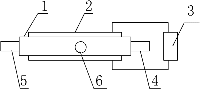
[0028] The flat-plate dielectric barrier discharge atomic vapor generator provided in this embodiment includes a cuboid sample chamber 1 surrounded by quartz glass; an electrode 2 is attached to two opposite walls in the length direction of the sample chamber 1, and the The two electrodes 2 are connected to the AC power supply 3 through wires; the two opposite walls in the width direction of the sample chamber 1 are respectively provided with a sample inlet 4 and an air outlet 5, and one wall in the height direction is provided with an air inlet port 6, the carrier gas can enter the sample chamber 1 through the gas inlet 6, forming a stable plasma discharge area in the sample chamber 1, and the sample to be measured enters the above discharge area through the sample inlet 4, and the The element to be tested in the sample to be tested forms atomic vapor, and then enters the instrument to be tested t...
Embodiment 2
[0030] Embodiment 2, round-through dielectric barrier discharge atomic vapor generator
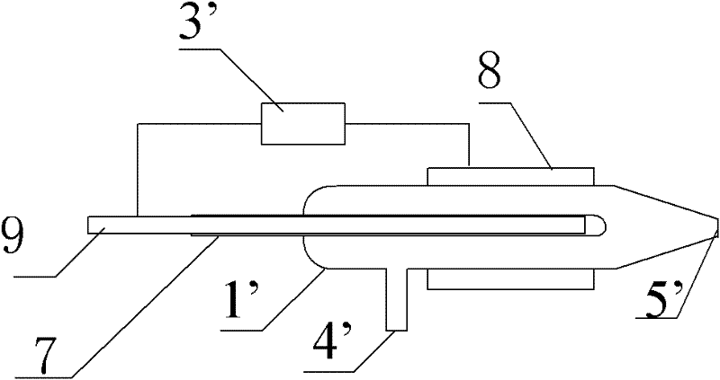
[0031] The round-through type dielectric barrier discharge atomic vapor generator provided in this embodiment includes a cylindrical sample chamber 1' surrounded by quartz glass, and one end of the sample chamber 1' is provided with a sleeve 7 with an open end, and the sleeve 7 The material is rubber, the open end of the sleeve 7 extends to the outside of the sample chamber 1', and the non-open end extends to the cavity of the sample chamber 1'; a ring electrode 8 is attached to the side wall of the sample chamber 1', and the sleeve 7 Filled with a central electrode 9, the ring electrode 8 and the central electrode 9 are connected to the AC power supply 3' through wires; a sample inlet 4' is also provided on the side wall of the sample chamber 1', and the sample opposite to the sleeve 7 is provided. The end of the chamber 1' is provided with a gas outlet 5', the carrier gas can enter the s...
Embodiment 3
[0033] Embodiment 3, round-through dielectric barrier discharge atomic vapor generator
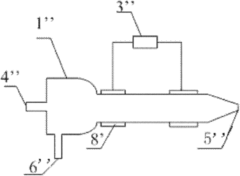
[0034] The round-through dielectric barrier discharge atomic vapor generator provided in this embodiment comprises a cylindrical sample chamber 1" surrounded by quartz glass, two ring electrodes 8' are attached to the outer wall of the sample chamber 1", two ring electrodes 8 'All are connected to the AC power supply 3" through wires; the two ends of the sample chamber 1" are respectively provided with a gas outlet 5" and a sample inlet 4", and on the side wall near the sample inlet 4" There is an air inlet 6", the carrier gas can enter the sample chamber 1" through the air inlet 6", forming a stable plasma discharge area in the sample chamber 1", and the sample to be tested enters the above discharge area through the inlet 4" , then under the action of plasma, the element to be tested in the sample to be tested forms atomic vapor, and then enters the instrument to be tested through the ga...
PUM
| Property | Measurement | Unit |
|---|---|---|
| power | aaaaa | aaaaa |
Abstract
Description
Claims
Application Information
 - R&D
- Intellectual Property
- Life Sciences
- Materials
- Tech Scout
- Unparalleled Data Quality
- Higher Quality Content
- 60% Fewer Hallucinations
Browse by: Latest US Patents, China's latest patents, Technical Efficacy Thesaurus, Application Domain, Technology Topic, Popular Technical Reports.
© 2025 PatSnap. All rights reserved.Legal|Privacy policy|Modern Slavery Act Transparency Statement|Sitemap|About US| Contact US: help@patsnap.com


