
Preparation device and preparation method for one-dimension photonic crystal band-stop filter

A technology of band-stop filter and dimensional photonic crystal, applied in the direction of optical waveguide light guide, light guide, optics, etc., can solve the problems of difficult operation, complex optical path, tedious and time-consuming, etc., and achieve the effect of simple operation, simple optical path and convenient operation

Inactive Publication Date: 2012-06-27
NINGBO UNIV
View PDF3 Cites 2 Cited by
  • Summary
  • Abstract
  • Description
  • Claims
  • Application Information

AI Technical Summary

Problems solved by technology

Because this method needs to use a beam splitter to divide the parallel light into two beams of parallel light with equal spot size, light intensity, and angle, and then use two symmetrical and parallel reflectors to separate the two parallel beams after beam splitting. At the same time, it is necessary to ensure that the incident angle of the two reflected parallel lights is consistent with that of the dichromate gelatin holographic dry plate. The optical path is very complicated, so the actual operation is cumbersome and time-consuming, and it is not easy to operate, and it is difficult for the operator to calibrate the optical path. High proficiency and technical level are required

Method used


Image

  • Preparation device and preparation method for one-dimension photonic crystal band-stop filter
  • Preparation device and preparation method for one-dimension photonic crystal band-stop filter
  • Preparation device and preparation method for one-dimension photonic crystal band-stop filter

Examples


Embodiment 1

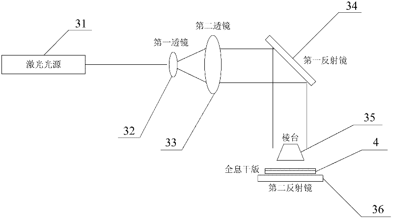
[0033] A preparation device for a one-dimensional photonic crystal band-stop filter, such as figure 1As shown, it includes a laser light source 31, a beam expander unit, a first reflector 34 and a second reflector 36. Generally, the first reflector 34 is placed at an angle of 45° to the horizontal plane, and the second reflector 36 is placed on the The red-sensitive photopolymer holographic dry plate 4 to be processed is placed, and the holographic photopolymer film of the red-sensitive photopolymer holographic dry plate 4 to be processed is facing upward, and the incident light emitted by the laser light source 31 passes through the optical beam expansion unit Form parallel beam expansion light, the light spot of the parallel beam expansion light emitted by the optical beam expansion unit is smaller than the surface of the holographic photopolymer film of the red-sensitive photopolymer holographic dry plate 4 to be processed, and the parallel light beam emitted by the light be...

Embodiment 2

[0038] This embodiment is a method for preparing a one-dimensional photonic crystal band-stop filter using the preparation device of Embodiment 1, which includes the following steps:

[0039] ① Turn on the He-Ne laser and let it warm up for more than 1 hour.

[0040] ②Take out the red-sensitive photopolymer holographic dry plate to be processed from the refrigerator, and place it in the laboratory for more than 30 minutes at room temperature.

[0041] ③The He-Ne laser emits red light with a wavelength of 632.8nm, and the red light passes through the first lens and the second lens of the beam expansion unit to form parallel beam expansion light.

[0042] ④The parallel expanded beams are reflected by the first reflector and then vertically incident on the prism as the non-diffraction stop, and the part of the expanded beam with uniform light intensity passing through the prism is incident vertically on the second reflector.

[0043] ⑤Finely adjust the pitch angle of the first r...

Embodiment 3

[0055] The steps ① to ⑥ and step ⑨ of the preparation method of the one-dimensional photonic crystal band-stop filter in this embodiment are the same as the steps ① to ⑥ and step ⑨ of the preparation method described in Example 2. The preparation method of the present embodiment Steps ⑦ and ⑧ are respectively: ⑦Remove the light screen, expose the red-sensitive photopolymer holographic dry plate to be treated for 30 seconds and then put it back into the light screen, then take out the exposed red-sensitive photopolymer holographic dry plate, put it in the cassette Put it in the middle for about 10 minutes. ⑧ Put the red-sensitive photopolymer holographic dry plate after exposure into distilled water and let it stand for 15 seconds; then dehydrate it in a 40% isopropanol solution for 1 minute; then dehydrate it in a 60% isopropanol solution Dehydration for 1 minute; then dehydration in 80% isopropanol solution for 15 seconds; finally dehydration in 100% isopropanol solution unti...


PUM


Abstract

The invention discloses a preparation device and a preparation method for a one-dimension photonic crystal band-stop filter. The preparation device comprises a laser light source, a light beam expansion unit, a first reflection mirror and a second reflection mirror, wherein the included angle between the first reflection mirror and the horizontal plane is 44 to 46 DEG C, a red-sensitive photopolymer holographic plate to be treated is placed on the second reflection mirror, incidence light emitted out by the laser light source forms parallel beam expansion light after passing through the light beam expansion unit, the beam expansion light is directly emitted onto the holographic plate through being reflected by the first reflection mirror, the transmitted beam expansion beam is vertically emitted onto the second reflection mirror, the parallel reflection light reflected by the second reflection mirror and the directly emitted beam expansion light form two beams of coherence light in opposite directions inside the holographic plate, and the holographic plate is exposed. The preparation device has the advantages that a light path is simple, the cost is low, in addition, only the single beam light is adopted to be vertically emitted onto the ed-sensitive photopolymer holographic plate, and then, the second reflection mirror is utilized, so two beams of coherence light: the upper beam of coherence light and the lower beam of coherence light are formed inside the holographic plate, and the operation is very convenient.

Description

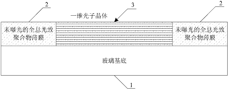
technical field [0001] The invention relates to a manufacturing technology of a photonic crystal filter, in particular to a manufacturing device and a manufacturing method of a one-dimensional photonic crystal band-stop filter. Background technique [0002] In 1987, Eli Yablonovitch of Bell Communications Institute and Sajeev John of Princeton University first proposed the concept of photonic crystal, which is a material structure whose dielectric constant (refractive index) changes periodically in space. So far, the theoretical and applied research of photonic crystals has developed rapidly, and various types of photonic crystals have been produced, among which one-dimensional photonic crystals, as the simplest structure, have been extensively studied and applied. One-dimensional photonic crystals are composed of media with different refractive indices arranged periodically in one-dimensional direction, similar to optical multilayer dielectric films, which have obvious phot...

Claims


Application Information

Patent Timeline
Patent Type & Authority Applications(China)
IPC IPC(8): G02B6/138G02B6/13
Inventor 张斌陶卫东潘雪丰董建峰王勇
Owner NINGBO UNIV
Learn More