Piezoelectric coupler and power circuit thereof

A power supply circuit and coupler technology, applied in circuits, piezoelectric/electrostrictive/magnetostrictive devices, high-efficiency power electronic conversion, etc., can solve problems such as low temperature stability, high labor costs, and low conversion efficiency , to achieve the effects of no electromagnetic interference, high conversion efficiency, and low cost

Inactive Publication Date: 2012-06-27
MORNSUN GUANGZHOU SCI & TECH
View PDF6 Cites 16 Cited by
  • Summary
  • Abstract
  • Description
  • Claims
  • Application Information

AI Technical Summary

Problems solved by technology

[0014] The technical problem to be solved by the present invention is to overcome the problems of complicated process and high labor cost when the switching power supply is isolated by electromagnetic transformer in the past, and the temperature stability of the inductor and capacitor connected to the circuit as discrete components in the previous capacitive isolation scheme Not high, low conversion efficiency and EMI problems

Method used


Image

  • Piezoelectric coupler and power circuit thereof
  • Piezoelectric coupler and power circuit thereof
  • Piezoelectric coupler and power circuit thereof

Examples


Embodiment 1

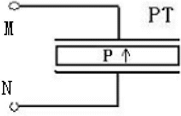
[0063] Pic 4-1 with Figure 4-2 It is a perspective view and a side view of the piezoelectric coupler PT according to the first embodiment of the present invention. The piezoelectric coupler PT provided by this embodiment is a rectangular one-piece piezoelectric body with four electrodes, and the upper surface of the piezoelectric body is There are two isolated input branch electrodes and two isolated output branch electrodes on the lower surface of the piezoelectric body; the piezoelectric resonator is polarized along the thickness direction from the input branch electrodes to the output branch electrodes, and the upper and lower corresponding input branch electrodes A resonant branch is formed between the electrodes and the output branch electrodes respectively. The shaded part in the figure represents the electrodes. The four electrodes on the left, right, up and down of the piezoelectric body are symmetrical and equal. One side, that is, the input branch electrode M1 and...

Embodiment 2

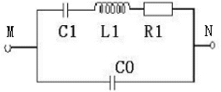
[0067] Figure 6-1 A second embodiment of the piezoelectric coupler of the present invention is shown, Figure 6-2 It is the equivalent deformation of the piezoelectric coupler of this embodiment. The difference between the piezoelectric coupler of this embodiment and the first embodiment is that firstly, the piezoelectric resonator forming the resonance branch of this embodiment is composed of two discrete piezoelectric The resonator is composed of PT1 and PT2, and the resonator is a disc type that uses the radial vibration mode to resonate. The two discrete piezoelectric resonators are equal in size, have the same polarization direction, and have the same resonant frequency; the two discrete piezoelectric resonators The electric harmonic oscillators each form a resonance branch. Such as Figure 6-1 As shown in , the upper and lower surfaces of the wafer vibrator are covered with electrodes, and the polarization direction is along the thickness direction. The piezoelectric...

Embodiment 3

[0070] On the basis of Embodiment 1, this embodiment provides a piezoelectric coupler with a multilayer structure, which consists of at least three layers of odd-numbered single-layer piezoelectric bodies stacked to form a multi-layer structure piezoelectric body. The structure of the electric body is the same as that of the piezoelectric body in Embodiment 1; the electrodes between the individual layers of the stacked piezoelectric coupler are shared as the inner electrodes of the stacked piezoelectric coupler; the stacked piezoelectric coupler is also It includes four side electrodes arranged along the thickness direction, through the isolation strips arranged at intervals between the electrodes of each layer, the two isolated input electrodes, the odd-numbered layer and the even-numbered layer, are respectively turned on, and two isolated output electrodes The odd-numbered layers and the even-numbered layers of the electrodes are respectively turned on. The above-mentioned ...


PUM


Abstract

The invention discloses a piezoelectric coupler and a power circuit thereof. The piezoelectric coupler and the power circuit thereof are mainly used in the occasion that input and output need to be isolated in a micropower switch power supply or in a low-power switch power supply. The piezoelectric coupler comprises two resonant branches used for piezoelectric coupling; each resonant branch is composed of piezoelectric harmonic oscillators; by applying the power circuit of the piezoelectric coupler, an electric signal of a primary-side topology is in direct resonant coupling with an auxiliary-side topology through a first resonant branch of the piezoelectric coupler; and a loop is formed through the other resonant branch of the piezoelectric coupler after loading. The piezoelectric coupler and the power circuit provided by the invention can be used for solving the problems that the process is complex and the manpower cost is high when the former switch power supply is isolated by adopting an electromagnetic transformer, and the problems of low temperature stability, low transformation rate and electro-magnetic interference (EMI) when an inductance and a capacitance as discrete components are connected on the circuit in a capacitance isolated scheme.

Description

technical field [0001] The invention relates to a piezoelectric coupler and a power supply circuit based on the piezoelectric coupler; in particular, it relates to a piezoelectric coupler and a power supply circuit which are applied to micro-power and low-power switching power supply occasions and are isolated between input and output. Background technique [0002] (1) Regarding electromagnetic transformers [0003] At present, most of the switching power supply technologies use electromagnetic transformers to realize the electrical isolation of the primary and secondary sides. The electromagnetic transformer winds two or more windings on the same magnetic core, and achieves the purpose of energy transmission while realizing the change of primary and secondary voltage, current, and impedance according to the principle of electromagnetic induction. Electromagnetic transformers have the advantages of high transmission power density and good load regulation, and are widely use...

Claims


Application Information

Patent Timeline
Patent Type & Authority Applications(China)
IPC IPC(8): H01L41/107H02M3/335
CPCY02B70/1433Y02B70/10
Inventor 胡健仁黄天华余凤兵
Owner MORNSUN GUANGZHOU SCI & TECH
Why Eureka
Try Eureka