Micro-band dual-mode band-pass filter based on double-end short-circuit resonator

A resonator and filter technology, applied to circuits, waveguide devices, electrical components, etc., to achieve high suppression and broadband effects

Inactive Publication Date: 2012-06-27
XIDIAN UNIV
View PDF3 Cites 11 Cited by
  • Summary
  • Abstract
  • Description
  • Claims
  • Application Information

AI Technical Summary

Problems solved by technology

[0004] The purpose of the present invention is to address the deficiencies in the prior art, and propose a dual-mode bandpass filter based on a double-terminal short-circuit resonator, so as to flexibly realize the deformation of various structural forms, widen the bandwidth to more than 30%, and meet modern Communication system requires flexible and changeable filter bandwidth design

Method used


Image

  • Micro-band dual-mode band-pass filter based on double-end short-circuit resonator
  • Micro-band dual-mode band-pass filter based on double-end short-circuit resonator
  • Micro-band dual-mode band-pass filter based on double-end short-circuit resonator

Examples


Embodiment 1

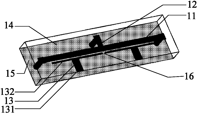
[0033] refer to figure 1 and figure 2 , the present invention is mainly composed of a linear double-terminal short-circuit microstrip resonator 11, a short-circuit stub 12, a pair of symmetrical input and output "T"-shaped feeders 13, a microstrip dielectric plate 14, and a metal ground plate 15. in:

[0034] The microstrip dielectric substrate 14 is a single-sided copper-clad dielectric substrate with a dielectric constant of 2.65 and a thickness of 1 mm;

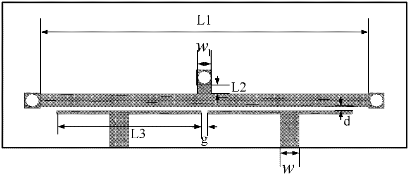
[0035] The linear double-terminal short-circuit microstrip resonator 11 is realized by copper skin, processed on the upper surface of the microstrip dielectric substrate 14, and the two ends of the resonator 11 are connected to the metal floor 15 through via holes, and the microstrip resonator 11 the length L 1 =48mm, equal to one waveguide wavelength, the corresponding resonant frequency ε e is the effective dielectric constant of the microstrip dielectric substrate 14;

[0036] The short-circuit stub 12 is loaded...

Embodiment 2

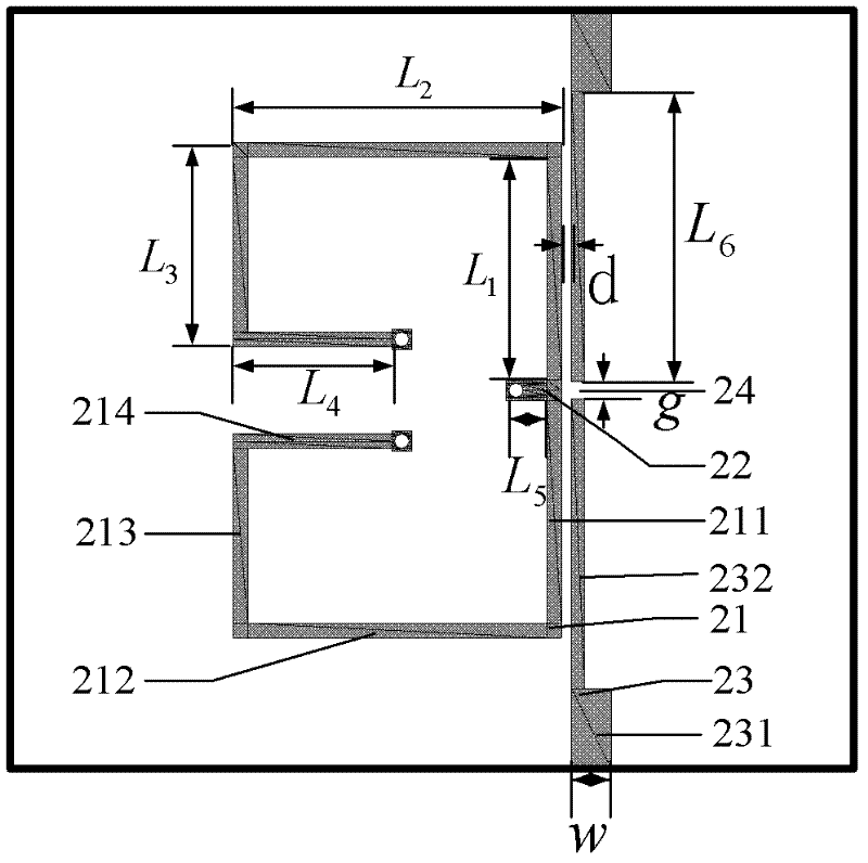
[0040] refer to image 3 , the present invention is mainly composed of a folded double-terminal short-circuit microstrip resonant ring 21, a short-circuit stub 22, and a pair of input and output feeders 23. The microstrip dielectric substrate is the same as that in Embodiment 1. in:

[0041] Folded double-terminal short-circuited microstrip resonant ring 21 is realized by copper skin, processed on the upper surface of the microstrip dielectric substrate, and realizes the short circuit at both ends of the resonant ring 21 through via holes. The total length of the microstrip resonant ring 21 is: 2×( L 1 +L 2 +L 3 +L 4 ) = 108mm, which is equal to a waveguide wavelength, corresponding to the resonant frequency f 0 = c / { 2 × ( L 1 + L 2 + ...

Embodiment 3

[0046] refer to Figure 4 , the present invention is mainly composed of a closed double-ended short-circuit square microstrip resonant ring 31, a center-loaded short-circuit branch 32, a pair of input and output "L"-shaped feeders 33, and an "L"-shaped microstrip line 34. The microstrip dielectric substrate Same as in Example 1. in:

[0047] The closed double-terminal short-circuit square ring microstrip resonator 31 is realized by copper skin, processed on the upper surface of the microstrip dielectric substrate, and any corner position of the square ring resonator 31 is short-circuited through the via hole, and the closed square ring microstrip resonates The total length of the device 31 is 4L 1 =77.4mm, equal to one waveguide wavelength, the corresponding resonant frequency ε e is the effective dielectric constant of the microstrip dielectric substrate, where L 1 =19.35mm.

[0048] The short-circuited microstrip stub 32 is loaded on the diagonal position of the short...


PUM


Abstract

The invention discloses a micro-band dual-mode band-pass filter based on a double-end short-circuit resonator, which mainly solves the problems of single form and quite narrow bandwidth of a traditional micro-band dual-mode filter. The filter comprises a pair of input / output T-shaped feeder lines (13), a micro-band medium plate (14), a metal grounding plate (15) and a micro-band resonator (11); the input / output T-shaped feeder lines (13) and the micro-band resonator (11) are arranged on the micro-band medium plate (14) above the metal grounding plate (15), wherein the resonator (11) is in a linear double-end short-circuit structure, and a short-circuit micro-band branch (12) is loaded in the center; the input / output T-shaped feeder lines (13) are horizontally arranged on one side of the micro-band resonator (11), and a gap (16) is formed between the input / output T-shaped feeder lines (13), so that the feeder lines are coupled, and out-of-band transmission zeros are added; and the micro-band dual-mode band-pass filter based on the double-end short-circuit resonator has the advantages that: the coupling of the feeder lines is realized, a design form is flexible and variable and the band is wide, and can be used for a wireless communication system.

Description

technical field [0001] The invention belongs to the technical field of electronic devices, and in particular relates to a microstrip dual-mode bandpass filter, which can be used for a radio frequency front end of a wireless communication system. Background technique [0002] Microwave radio technology has had a huge impact on the development of modern society, especially with the increasing number of microwave and millimeter wave communication services, spectrum resources are becoming increasingly tight, frequency band resources are divided more finely, and the requirements for wireless terminal equipment have become very harsh. Microstrip filters are urgently required to develop rapidly in the direction of high performance, miniaturization, low cost, and high integration. Research on miniaturized high-performance microstrip filters has attracted more and more attention. Traditional filter forms such as Butterworth and Chebyshev filters can only meet the high selectivity req...

Claims


Application Information

Patent Timeline
Patent Type & Authority Applications(China)
IPC IPC(8): H01P1/203
Inventor 孙守家吴边邓坤杨帅李雪峰梁昌洪
Owner XIDIAN UNIV
Why Eureka
Try Eureka