Ultra wideband switching reconfigurable antenna and method for realizing trapping of different frequencies

A technology for reconfiguring antennas and ultra-wideband, applied to antennas, antenna couplings, waveguide devices, etc., can solve problems such as complex structures, difficulties in meeting notch characteristics, and inability to work simultaneously

Inactive Publication Date: 2012-06-27
HARBIN ENG UNIV
View PDF4 Cites 23 Cited by
  • Summary
  • Abstract
  • Description
  • Claims
  • Application Information

AI Technical Summary

Problems solved by technology

[0004] The present invention is to solve the potential interference between the ultra-wideband antenna and the narrowband system, and it is difficult to meet the specific requirements of notch characteristics. The problem with broadband status

Method used


Image

  • Ultra wideband switching reconfigurable antenna and method for realizing trapping of different frequencies
  • Ultra wideband switching reconfigurable antenna and method for realizing trapping of different frequencies
  • Ultra wideband switching reconfigurable antenna and method for realizing trapping of different frequencies

Examples


specific Embodiment approach 1

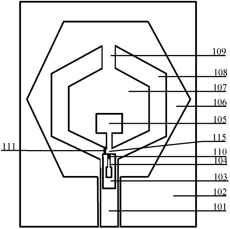
[0024] DETAILED DESCRIPTION OF THE PREFERRED EMBODIMENTS 1. An ultra-wideband switch reconstruction antenna, which includes a rectangular resonant cavity 103, a second stepped impedance tuning rod 104, a first stepped impedance tuning rod 105, a regular hexagonal wide slot structure 106, a regular hexagonal Resonant cavity 107, regular hexagonal radiation unit 108, first slot 109, first switch 110, second switch 111, coplanar waveguide feeding structure 113 and resonant cavity high impedance line 115, the coplanar waveguide feeding structure 113 includes the coplanar waveguide feeding signal stripline 101, the coplanar waveguide ground plane 102 and the second slot 114,

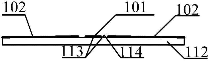
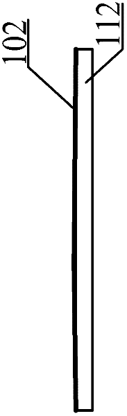
[0025]The coplanar waveguide ground plane 102 is printed on the dielectric substrate 112, the coplanar waveguide feed signal stripline 101 is located inside the coplanar waveguide ground plane 102 and printed on the dielectric substrate 112, and the second slot 114 is located in the coplanar waveguide Between...

specific Embodiment approach 2

[0028] Embodiment 2. The difference between this embodiment and Embodiment 1 is that: the dielectric constant of the dielectric substrate 112 is 2.65, and the dielectric loss tangent is less than 10 -2 , and its size is consistent with the coplanar waveguide ground plane 102 .

specific Embodiment approach 3

[0029] Embodiment 3. The difference between this embodiment and Embodiment 1 is that the three axisymmetric diagonals of the regular hexagonal radiation unit 108 coincide with the three axisymmetric diagonals of the regular hexagonal wide groove structure 106. , the first slot 109 is located at the top of the regular hexagonal radiation unit 108 , and the first slot 109 , the first stepped impedance tuning rod 105 and the second stepped impedance tuning rod 104 are on a straight line.

[0030] In the present invention, switching between the UWB antenna and the notch UWB antenna is realized by turning on and off the first switch 110 and the second switch 111 . The regular hexagonal resonant cavity 107 loaded by the stepped impedance tuning rod 105 and the rectangular resonant cavity 103 loaded by the stepped impedance tuning rod 104 generate two notches. Figure 11 It is a schematic diagram of the structure of the switch in the closed state. The ultra-wideband antenna generates...


PUM


Abstract

The invention relates to an ultra wideband switching reconfigurable antenna and a method for realizing trapping of different frequencies, and aims to solve the problems of limitation of the width of a feeder line on the antenna, potential interference between an ultra wideband system and a narrow-band system, difficulty in the satisfaction of needs in specific trapping characteristics, large volume, complex structure and incapability of simultaneously working in an ultra wideband state and a trapping ultra wideband state. The ultra wideband switching reconfigurable antenna comprises an orthohexagonal wide-slot structure, switches, a gap in the top of the orthohexagonal wide-slot structure, a coplanar waveguide ground plane and a coplanar waveguide feed structure. A double-trapping characteristic is realized by etching a resonant cavity loaded by a stepped-impedance tuning wand on each of an orthohexagonal radiation unit and a coplanar waveguide feed signal strip line. Structural parameters of two resonant cavity filters are regulated to change the resonance frequencies of the two filters to make the two filters work at different frequencies, so that two adjustable trapping frequencies can be generated. The antenna and the method are applied in the field of wireless communication.

Description

technical field [0001] The invention relates to an antenna, in particular to an ultra-wideband switch reconfiguration antenna, and the invention also relates to a notch method for realizing different frequencies. Background technique [0002] In recent years, with the rapid development of wireless communication technology, people have higher and higher requirements for wireless communication. Especially in recent years, with the rapid growth of personal wireless communication services, mobile communication is developing in the direction of broadband, high gain, and environment-friendly development. Therefore, the frequency bands of mobile communications are becoming more and more concentrated, and the phenomenon of multi-band overlapping is becoming more and more serious. Since the U.S. Federal Communications Commission announced 3.1GHz-10.6GHz as the indoor ultra-wideband communication frequency band in 2002, experts, scholars and related companies at home and abroad have ...

Claims


Application Information

Patent Timeline
Patent Type & Authority Applications(China)
IPC IPC(8): H01Q1/52H01Q3/22H01Q3/24H01Q1/36H01P1/207H04B1/7163
Inventor 李迎松李文兴刘乘源
Owner HARBIN ENG UNIV
Why Eureka
Try Eureka