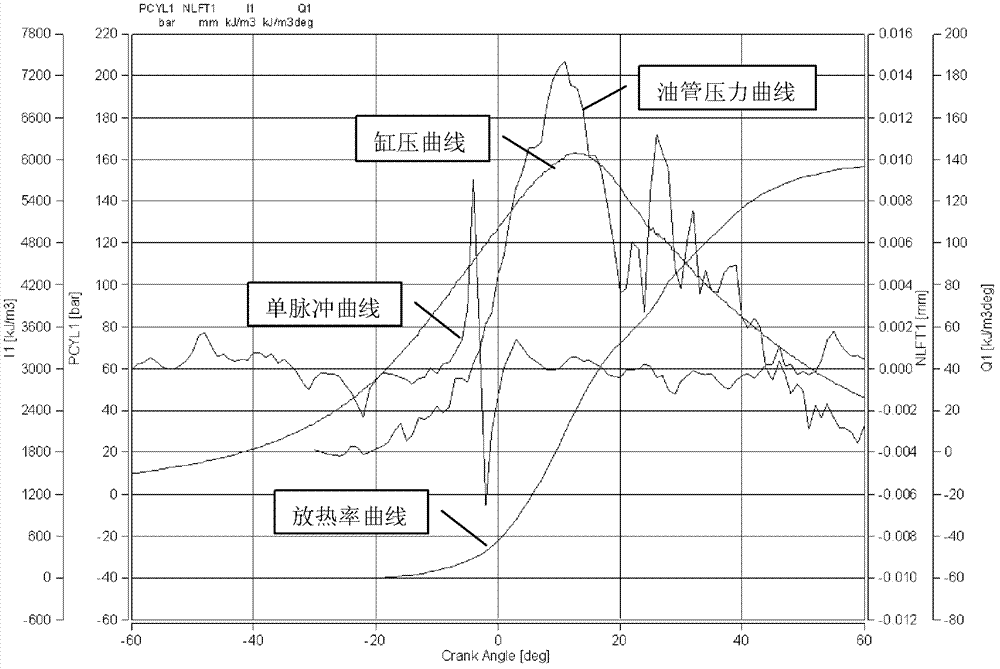
Diesel engine indicator diagram measuring method
A measurement method and diesel engine technology, applied in power metering, measuring devices, internal combustion engine testing, etc., can solve problems such as inaccurate data, and achieve the effect of avoiding error factors and improving accuracy
- Summary
- Abstract
- Description
- Claims
- Application Information
AI Technical Summary
Problems solved by technology
Method used
Image
Examples
Embodiment Construction
[0019] Since the lower the speed of the diesel engine, the closer the calibrated top dead center is to the actual physical top dead center of the diesel engine, therefore, the top dead center of the diesel engine can be calibrated approximately at the idle speed of the diesel engine. However, although the angular drift of the maximum pressure is the smallest at the idle speed, this phenomenon cannot be ignored. Therefore, it is necessary to increase the sensor to measure the physical top dead center of the diesel engine. The method of measuring the physical top dead center is as follows:
[0020] Crank the diesel engine to 0°, at this time, cylinder 1 is at top dead center. Then paste a thin iron sheet with a height of about 15 mm on the timing plate of the diesel engine, and the iron sheet is located in the middle of the sensor contact.
[0021] Both the timing plate and the end of the generator can be pasted with iron sheets, but the timing plate is finally selected because...
PUM
| Property | Measurement | Unit |
|---|---|---|
| height | aaaaa | aaaaa |
Abstract
Description
Claims
Application Information
 - R&D
- Intellectual Property
- Life Sciences
- Materials
- Tech Scout
- Unparalleled Data Quality
- Higher Quality Content
- 60% Fewer Hallucinations
Browse by: Latest US Patents, China's latest patents, Technical Efficacy Thesaurus, Application Domain, Technology Topic, Popular Technical Reports.
© 2025 PatSnap. All rights reserved.Legal|Privacy policy|Modern Slavery Act Transparency Statement|Sitemap|About US| Contact US: help@patsnap.com


