
Broadband dual-polarization antenna and radiating unit thereof

A dual-polarized antenna and radiating element technology, which is applied to antenna element combinations with different polarization directions, radiating element structure forms, antennas, etc. characteristics, the balun structure is not suitable for coupled feeding, etc., to achieve the effect of easy die-casting, firm and reliable structure, and improved intermodulation index

Active Publication Date: 2012-07-04
COMBA TELECOM TECH (GUANGZHOU) CO LTD
View PDF9 Cites 27 Cited by
  • Summary
  • Abstract
  • Description
  • Claims
  • Application Information

AI Technical Summary

Problems solved by technology

In the above two patents, in addition to the large size of the vibrator arm, the balun structure is not suitable for coupling feeding, and the bandwidth is limited, which limits its application range
[0008] For further reference, please refer to US 6933906 Patent Announcement, the vibrator arm used in it is a square structure, and the balun adopts a closed cylindrical structure, which is beneficial to realize coupling feeding and broadband characteristics, but the inner wall of the closed balun is not easy to ensure the quality of electroplating, so the alternating current of the radiation unit It is not easy to guarantee the tuning characteristics, and the isolation characteristics between different polarizations of the vibrator are poor; CN 101707291A patent application discloses a broadband radiation unit, which also does not solve the problem of large dimen- The closed hollow square column structure still cannot achieve the technical effect of ensuring the intermodulation characteristics of the radiation unit
[0009] From the above analysis, it can be seen that in the prior art, for broadband dual-polarized antennas, there is a certain contradiction between the size of the radiation oscillator used and the electrical performance.

Method used


Image

  • Broadband dual-polarization antenna and radiating unit thereof
  • Broadband dual-polarization antenna and radiating unit thereof
  • Broadband dual-polarization antenna and radiating unit thereof

Examples


Embodiment Construction

[0035] Below in conjunction with accompanying drawing and embodiment the present invention will be further described:

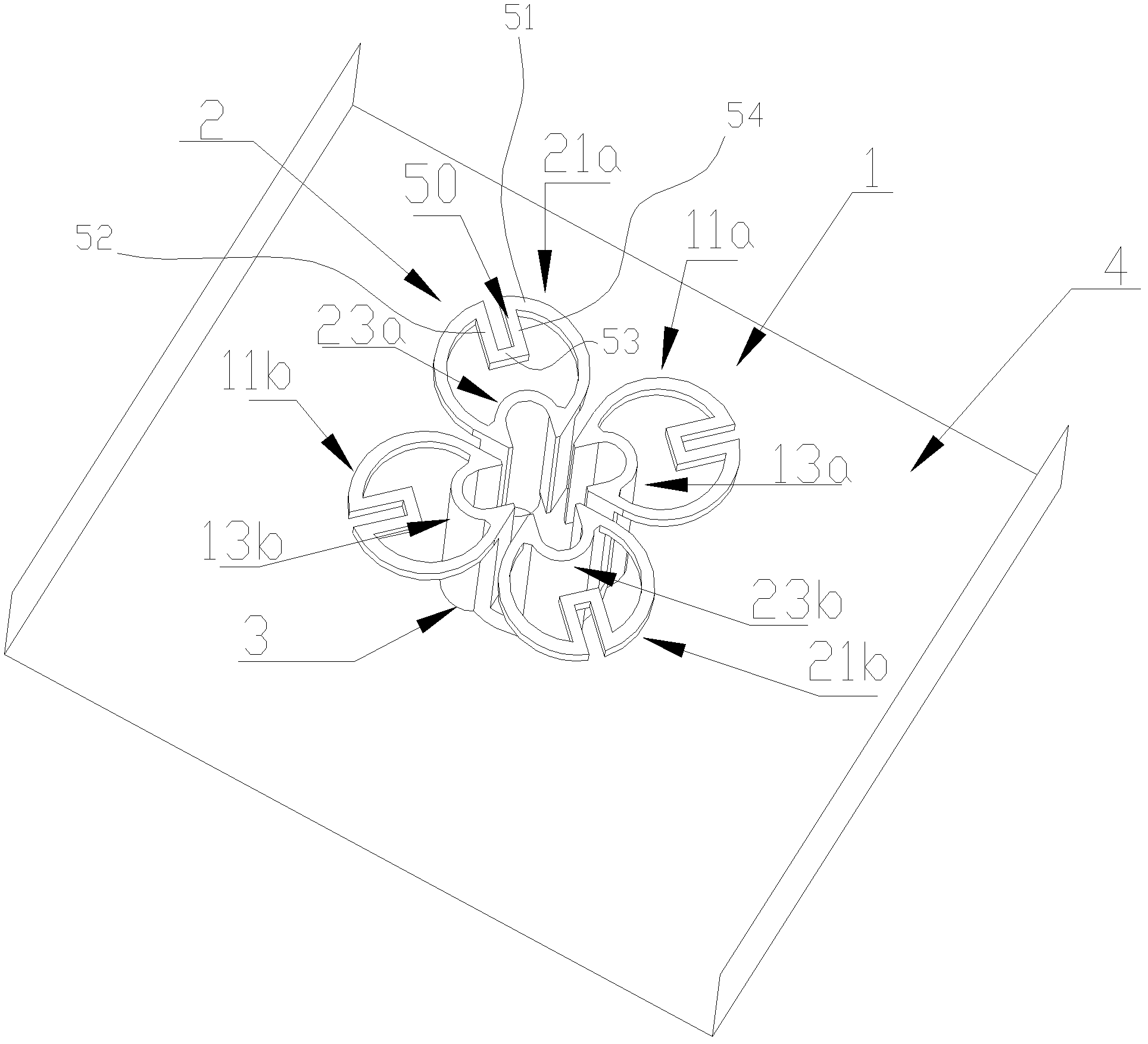
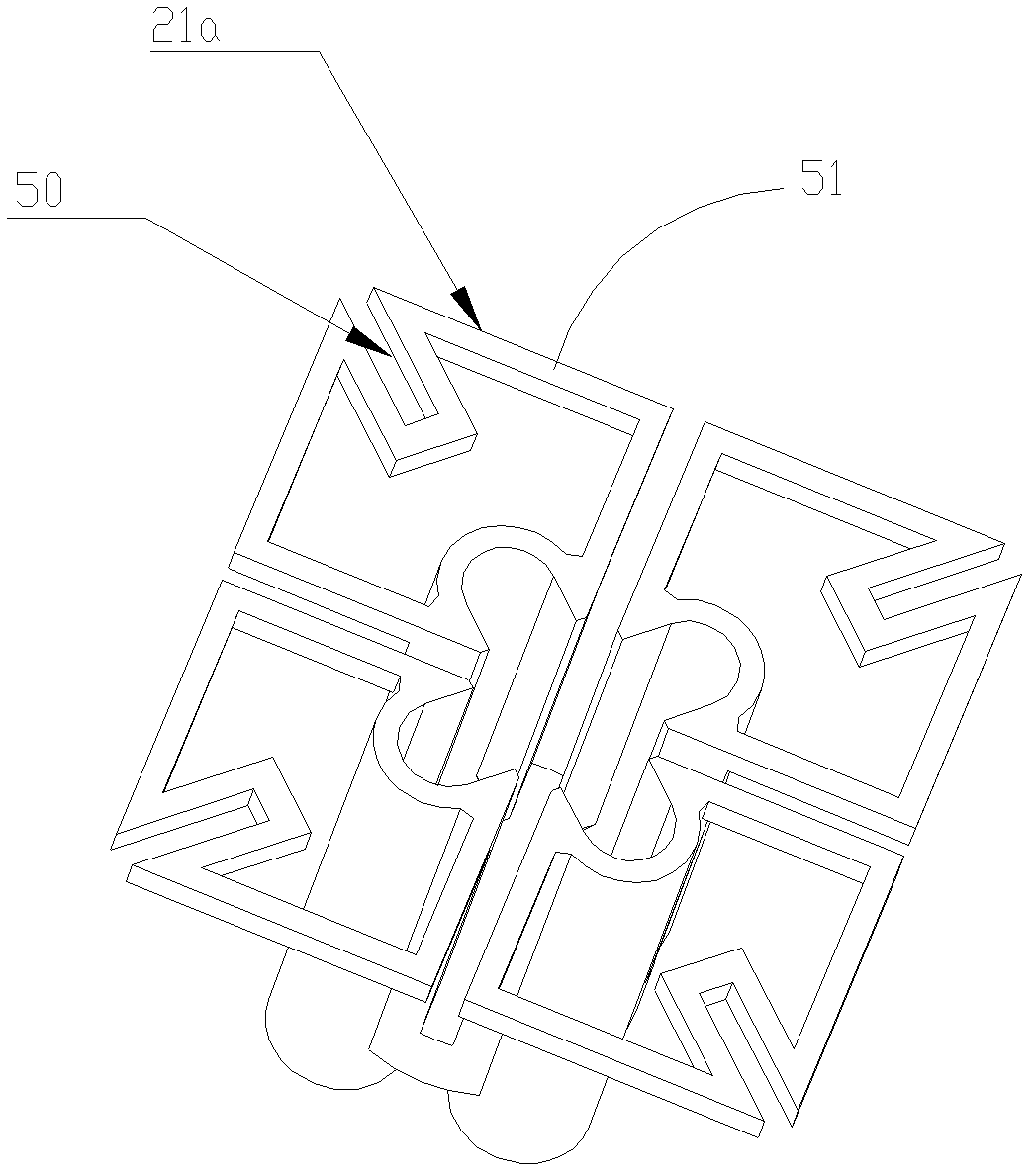
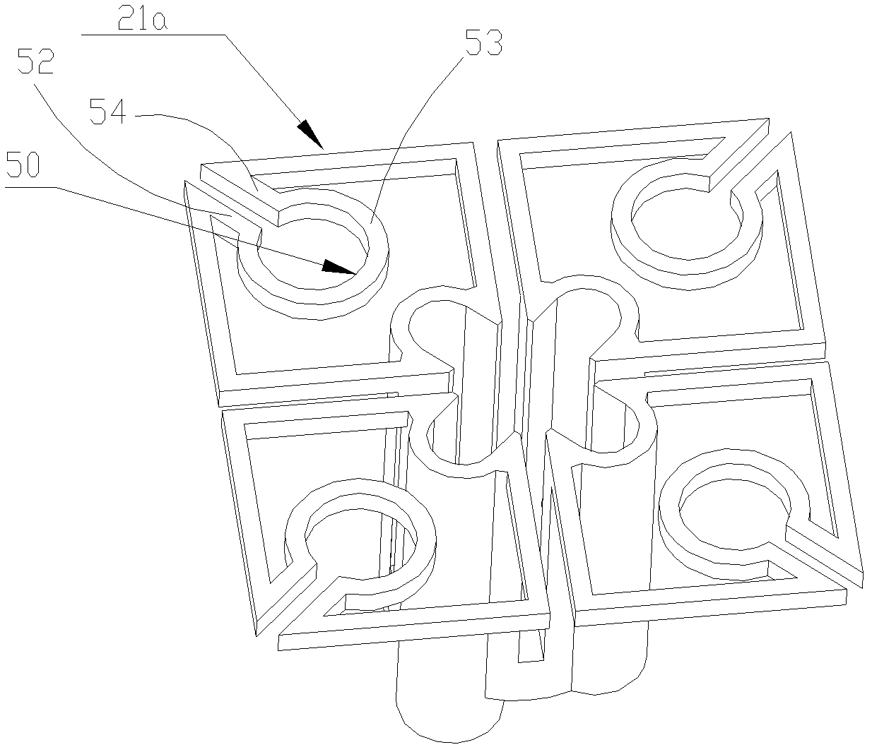
[0036] see figure 1The perspective view of the first embodiment of the broadband dual-polarized antenna radiating unit of the present invention is shown. The radiating unit includes two pairs of symmetrical oscillators 1 and 2, and each pair of symmetrical oscillators 1 or 2 includes a pair of radiation arms (11a and 11b are a pair, 21a and 21b are a pair, and the bottom same), each radiation arm 11a, 11b, 21a, 21b is supported by a balun 13a, 13b, 23a, 23b, one end of the balun 13a, 13b, 23a, 23b is fixed on the metal reflector 4 of the antenna, and the other One end is fixedly connected to a radiation arm 11a, 11b, 21a, 21b to form a support for the corresponding radiation arm 11a, 11b, 21a, 21b, and the balun 13a, 13b, 23a, 23b is connected to the corresponding radiation arm 11a, 11b, 21a , 21b is located at one end of the radiation arm 11a, 11b, 21a, 21...


PUM


Abstract

The invention discloses a broadband dual-polarization antenna and a radiating unit thereof. The radiating unit comprises two pairs of symmetrical dipoles with mutually orthogonal polarization, and each pair of symmetrical dipoles comprises a pair of radiation arms and a pair of balens used for being fixed on a metal reflection plate and implementing same side supporting to each radiation arm at the end where the radiation arms are close. Each radiation arm is arranged on a same reference plane, the whole radiating unit and the geometric center of the reference plane are of a symmetrical structure, the reference plane extends towards the bottom directions of the baleens to form a space which is defined as a containing space, each radiation arm is in a shape of closed single line, a main body located on the reference plane exists, the radiation arm is provided with an expanding portion extending to the containing space in a bending mode from the main body of the radiation arm at one end of the radiation arm far away from the corresponding balen. The broadband dual-polarization antenna and the radiating unit lengthen path length of current in the radiation arm by fully using space, thereby being capable of reducing size of the radiation arm based on appointed electrical specifications.

Description

【Technical field】 [0001] The invention relates to the field of mobile communication antennas, in particular to a broadband dual-polarized antenna and a radiation unit thereof. 【Background technique】 [0002] With the development of mobile communication, higher requirements are placed on the bandwidth and performance of base station antennas. [0003] With the establishment and operation of the third-generation mobile communication network, and the wide application of broadband wireless networks such as WLAN and WiMax, the market has put forward a huge demand for broadband antennas, especially those that can cover the following communication standards: GSM1800, DCSCDMA 1900, IMT-2000 , TD-CDMA, WLAN, WiMax and other 1.7GHz 2.7GHz band broadband antennas. [0004] With the application and rapid development of wireless technology, the electromagnetic environment is becoming more and more complex, which puts forward higher and higher requirements for the design of mobile commun...

Claims


Application Information

Patent Timeline
IPC IPC(8): H01Q21/24H01Q19/10H01Q1/36
CPCH01Q19/10H01Q21/24H01Q1/36H01Q9/16
Inventor 肖勇才薛锋章赖展军
Owner COMBA TELECOM TECH (GUANGZHOU) CO LTD
Learn More