Laser-pumped flowing nano-particle rare-earth ion laser

A technology for pumping lasers and rare earth ions, applied in the field of lasers, can solve problems such as the difficulty of a single fiber laser to achieve a 100-kilowatt output, serious thermal effects of solid-state lasers, and non-recyclable fuels, achieving good heat dissipation effect, large mode volume, Less waste heat generation effect

Active Publication Date: 2013-06-19
NAT UNIV OF DEFENSE TECH
View PDF2 Cites 3 Cited by
  • Summary
  • Abstract
  • Description
  • Claims
  • Application Information

AI Technical Summary

Problems solved by technology

[0011] In order to solve the problems of non-recyclable use of chemical laser fuel and bulky volume, and to overcome the serious thermal effect of solid-state lasers, the difficulty of achieving hundreds of kilowatt-level output of a single fiber laser, and in order to avoid the shortcomings that DPAL is very complicated to achieve effective pumping, the present invention A laser-pumped flowing nanoparticle rare earth ion laser with simple structure, less heat generation, fast heat dissipation, large mode volume, less environmental pollution, and reusable gain medium is proposed.

Method used


Image

  • Laser-pumped flowing nano-particle rare-earth ion laser
  • Laser-pumped flowing nano-particle rare-earth ion laser
  • Laser-pumped flowing nano-particle rare-earth ion laser

Examples


Embodiment 1

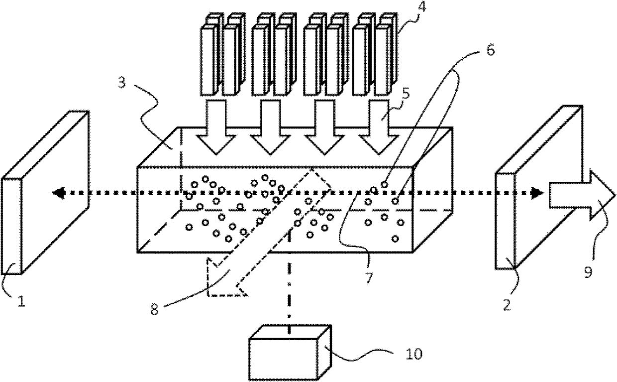
[0032] a kind of like Figure 1 ~ Figure 4 The laser-pumped flow nanoparticle rare earth ion laser of the present invention is shown, the laser includes a pump laser 4, a gas working chamber 3 and a resonant cavity.

[0033] The gas working chamber 3 of this embodiment is a rectangular parallelepiped of quartz glass coated with an anti-reflection film. The gas working chamber 3 is filled with a gain medium 6 that can be excited to a high energy state by the pump light 5 emitted by the pump laser 4. The gain medium 6 is mainly nanoparticles containing rare earth ions; the gain medium 6 in this embodiment is an average particle Yb with a diameter of 80nm 2 o 3 powder (the Yb 2 o 3 The powder was provided by Shanghai Institute of Ceramics with a purity of 99.9%). Nano Yb containing rare earth ions 2 o 3 After the powder is loaded into the gas working chamber 3, the circulation of the nano-rare earth ions, the oscillation output of the pump light 5 and the laser 7 can be co...

Embodiment 2

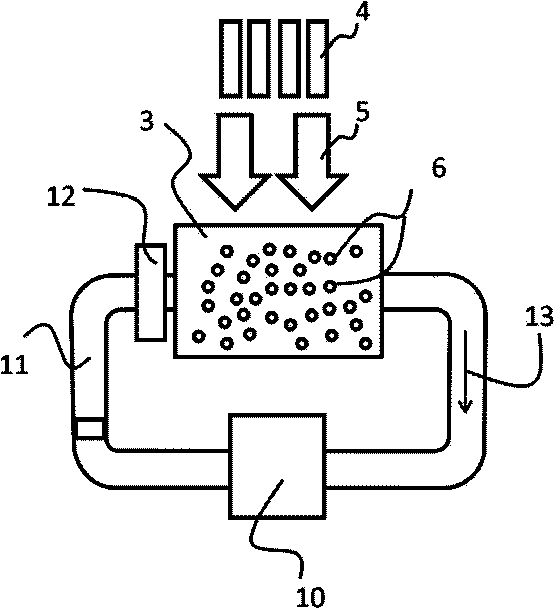
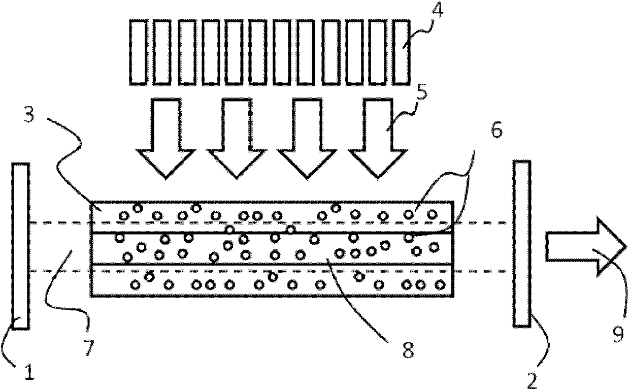
[0040] a kind of like Figure 4 The laser-pumped flow nanoparticle rare earth ion laser of the present invention shown, the gas laser includes a pump laser 4, a coupling mirror system 14, a gas working chamber 3 and a resonant cavity.

[0041] The gas working chamber 3 of this embodiment is a rectangular parallelepiped of quartz glass coated with an anti-reflection film. The gas working chamber 3 is filled with a gain medium 6 that can be excited to a high energy state by the pump light 5 emitted by the pump laser 4. The gain medium 6 is mainly nanoparticles containing rare earth ions; the gain medium 6 in this embodiment is an average particle Yb with a diameter of 80nm 2 o 3 powder (the Yb 2 o 3 The nanopowder was provided by Shanghai Institute of Ceramics with a purity of 99.9%). Nano Yb containing rare earth ions 2 o 3 After the powder is loaded into the gas working chamber 3, the circulation of the nano-rare earth ions can be controlled from a pair of working surfa...


PUM


Abstract

The invention discloses a laser-pumped flowing nano-particle rare-earth ion laser, which comprises a pump laser (4), a gas working chamber (3) and a resonant cavity, wherein a gain medium (6) which can be excited to a high energy state by pump light (5) emitted from the pump laser (4) is filled in the gas working chamber (3), and the gain medium (6) mainly contains rare-earth ion nano-particles. The gas working chamber (3) is communicated to a cycle control device (10) through a connecting pipeline (11). The flowing nano-particle rare-earth ion laser has the advantages of simple structure, less produced heat, fast heat dissipation, large mode volume, little environmental pollution, and the like, and the gain medium can be reused.

Description

technical field [0001] The invention belongs to the technical field of lasers, in particular to a high-energy laser using a special gain medium. Background technique [0002] At present, with the wide application of high-energy lasers in national defense and industry, the exploration of obtaining high-energy laser output has attracted more and more attention from researchers. A traditional laser consists of three parts: a gain medium, a pump source and a resonant cavity. Among them, the pump source provides energy for the gain medium to excite it to a high-energy state, and the resonator provides positive feedback and coupling output to continuously amplify the stimulated radiation and generate laser output. The factors that actually affect the development of lasers to high power include the energy of the pump source and the characteristics of the gain medium. Existing high-energy lasers include chemical lasers and solid-state lasers, and solid-state lasers include traditi...

Claims


Application Information

Patent Timeline
Patent Type & Authority Patents(China)
IPC IPC(8): H01S3/227B82Y20/00
Inventor 许晓军张汉伟王红岩杨子宁习锋杰
Owner NAT UNIV OF DEFENSE TECH
Why Eureka
Try Eureka