
Substrate for mounting semiconductor chip and method for producing same

A manufacturing method and semiconductor technology, applied in semiconductor/solid-state device manufacturing, semiconductor devices, semiconductor/solid-state device components, etc., can solve problems such as short-circuit faults, connection reliability, and wire-bondability degradation, and achieve good wire-bondability, Effect of Good Solder Connection Reliability

Inactive Publication Date: 2012-07-11
RESONAC CORP
View PDF7 Cites 7 Cited by
  • Summary
  • Abstract
  • Description
  • Claims
  • Application Information

AI Technical Summary

Problems solved by technology

[0006] However, as described in Non-Patent Document 2, it is known that the electroless nickel plating / electroless gold plating method has lower solder connection reliability and wire bondability after heat treatment than the electrolytic nickel plating / electrolytic gold plating method.
[0007] In addition, if electroless nickel plating is applied to the wiring, a phenomenon called bridging may occur between the wiring and an electroless nickel plating film may occur, which may cause a short circuit failure.

Method used


Image

  • Substrate for mounting semiconductor chip and method for producing same
  • Substrate for mounting semiconductor chip and method for producing same
  • Substrate for mounting semiconductor chip and method for producing same

Examples


no. 1 Embodiment approach

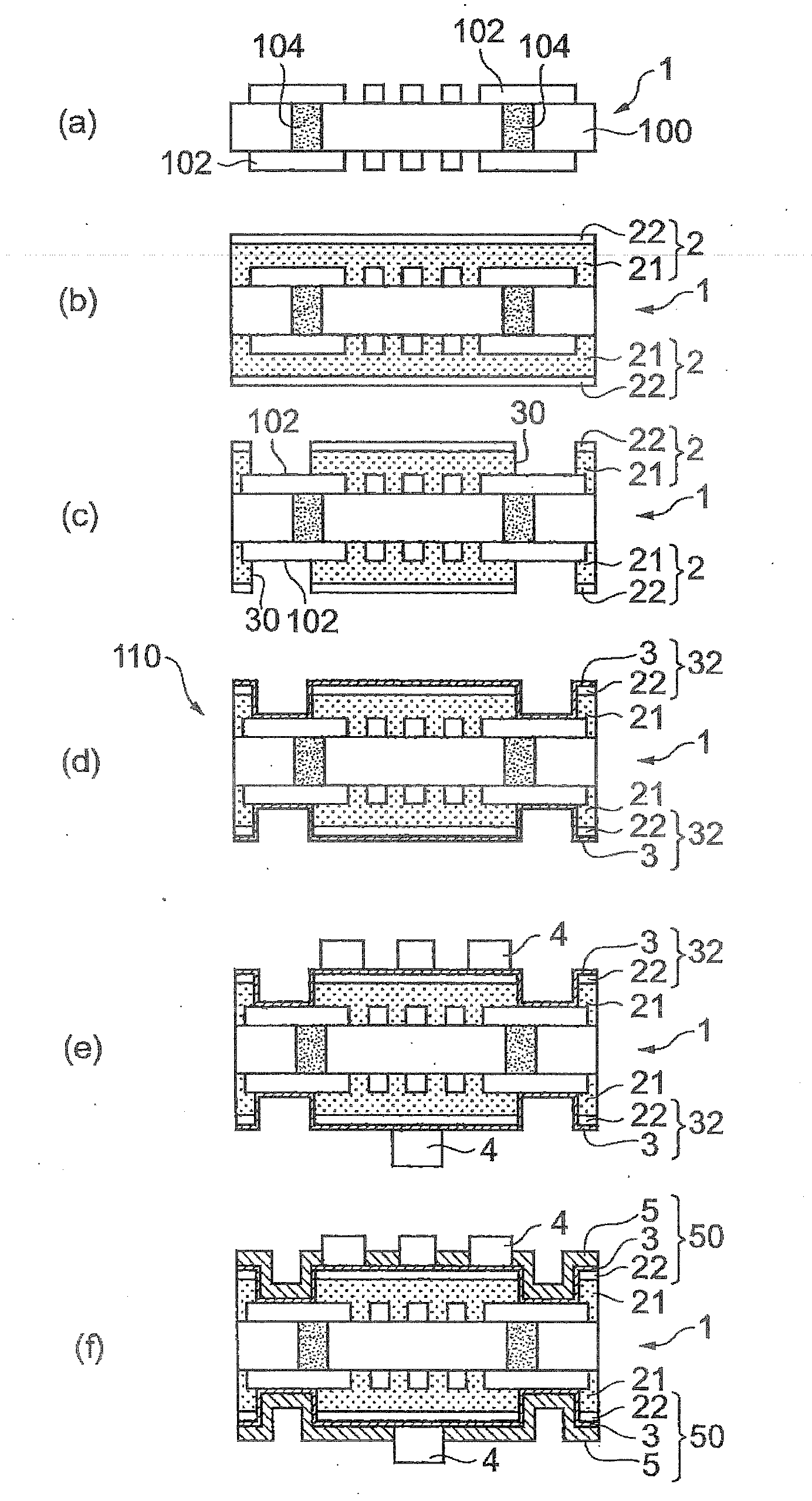
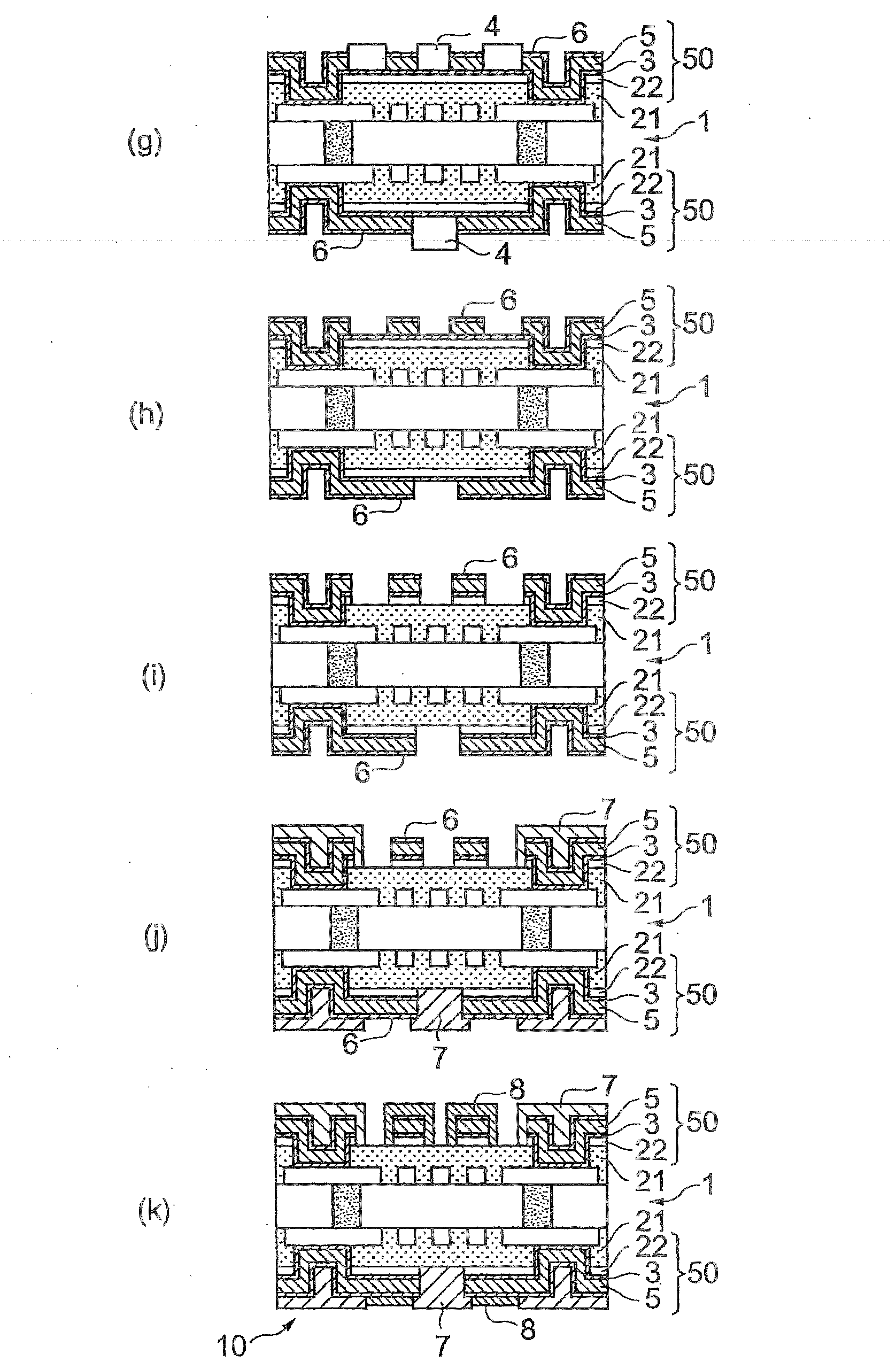
[0075] A preferred first embodiment of the method of manufacturing a substrate for mounting a semiconductor chip will be described below. figure 1 with 2 It is a process drawing which schematically shows the manufacturing method of the board|substrate for mounting a semiconductor chip concerning 1st Embodiment. This embodiment is an example of a method of manufacturing a substrate for mounting a semiconductor chip using a semi-additive method in which an outer layer circuit is formed using a resin with copper foil on the inner layer board.

[0076] In this embodiment, first, if figure 1 As shown in (a), the inner layer plate 1 is prepared. The inner-layer board 1 has: an inner-layer substrate 100, an inner-layer circuit 102 provided on its surface, and an inner-layer through-circuit formed to penetrate the inner-layer substrate and electrically connect the inner-layer circuits 102 on both surfaces. Hole 104. As each configuration in the inner layer board 1 , known configur...

no. 2 Embodiment approach

[0138] Next, a preferred second embodiment of the method of manufacturing a substrate for mounting a semiconductor chip will be described. Image 6 with 7It is a process drawing which schematically shows the manufacturing method of the board|substrate for mounting a semiconductor chip concerning 2nd Embodiment. This embodiment is an example of a method of manufacturing a substrate for mounting a semiconductor chip using a semi-additive method, and includes a step of forming a copper plating layer after laminating a composite film on an inner layer board.

[0139] In this embodiment, first, if Image 6 As shown in (a), the inner layer plate 1 is prepared. This inner layer panel 1 can be prepared in the same manner as in the first embodiment described above. Secondly, if Image 6 As shown in (b), the insulating layer 15 is formed by laminating or pressing a composite film on both surfaces of the inner layer board 1 . The composite film is a non-conductive film and is formed...

Embodiment 1

[0174] (Manufacturing of substrates for mounting semiconductor chips)

[0175] (1a) Preparation of the inner plate

[0176] First, if figure 1 As shown in (a), MCL-E-679 (manufactured by Hitachi Chemical Industries, Ltd., manufactured by Hitachi Chemical Industry Co., Ltd. trade name), the copper foil at unnecessary parts was removed by etching to form through-holes, and an inner-layer board (inner-layer board 1) having an inner-layer circuit formed on the surface was obtained.

[0177] (1b) Lamination of copper foil with resin

[0178] Such as figure 1 As shown in (b), MCF-7000LX (manufactured by Hitachi Chemical Industries, Ltd., trade name) coated with an adhesive (insulating layer 21) on a 3 μm thick copper foil 22 was heated at 170° C. 30kgf / cm 2 Under the condition of heating and pressing for 60 minutes, lamination is carried out.

[0179] (1c) Formation of IVH

[0180] Such as figure 1 As shown in (c), IVH30, which is a non-through hole with a diameter of 80 μm,...


PUM


Abstract

Disclosed is a method for producing a substrate for mounting a semiconductor chip, by which the formation of bridges can be reduced and excellent wire bonding performance and excellent solder joint reliability can be achieved even in cases when fine wiring is formed. Specifically disclosed is a method for producing a substrate for mounting a semiconductor chip, which comprises: a resist formation step wherein a resist is formed on a first copper layer of a laminate, which comprises an inner layer plate having an inner layer circuit on the surface and the first copper layer that is formed on the inner layer plate with an insulating layer therebetween, in regions other than the region that is to be a conductor circuit; a conductor circuit formation step wherein a conductor circuit is obtained by forming a second copper layer on the first copper layer by electrolytic copper plating; a nickel layer formation step wherein a nickel layer is formed on at least a part of the conductor circuit by electrolytic nickel plating; a resist removal step wherein the resist is removed; an etching step wherein the first copper layer is removed by etching; and a gold layer formation step wherein a gold layer is formed on at least a part of the conductor circuit by electroless gold plating.

Description

technical field [0001] The present invention relates to a semiconductor chip mounting substrate and a manufacturing method thereof. Background technique [0002] In recent years, in electronic equipment such as personal computers, mobile phones, wireless base stations, optical communication devices, servers, and routers, the miniaturization, weight reduction, high performance, and high functionality of the equipment have been progressing regardless of their size. In addition, the development of high-density packaging technologies such as SoC (System on a chip) and SiP (System In Package) is progressing in parallel with the increase in speed and functionality of LSIs such as CPUs, DSPs, and various memories. [0003] For this reason, multilayer wiring boards of a build-up system have begun to be used in semiconductor chip mounting substrates and mother boards. In addition, due to advances in mounting technology for packaging multiple pins with narrower pitches, substrates fo...

Claims


Application Information

Patent Timeline
Patent Type & Authority Applications(China)
IPC IPC(8): H01L23/12H01L21/60H05K3/24H05K3/46
CPCH05K3/4652H05K3/4644H05K3/244H05K3/108H01L2924/00013H05K3/062H01L21/4857H01L2924/0002Y10T29/49155Y10T29/49156Y10T29/49165H01L2224/13099H01L2224/13599H01L2224/05599H01L2224/05099H01L2224/29099H01L2224/29599H01L2924/00H01L23/12H05K3/24H05K3/46
Inventor 江尻芳则长谷川清樱井健久坪松良明
Owner RESONAC CORP
Learn More