

Active centrifugal gas-liquid separation device
A gas-liquid separation device, active technology, applied in the field of liquid separation and recovery, gas field, can solve the problems of decreased separation efficiency, high maintenance cost, large flow of washing liquid, etc., to relax the oxygen content range, reduce maintenance costs, reduce The effect of maintenance costs
- Summary
- Abstract
- Description
- Claims
- Application Information
AI Technical Summary
Problems solved by technology
Method used
Image

Examples
Embodiment 1
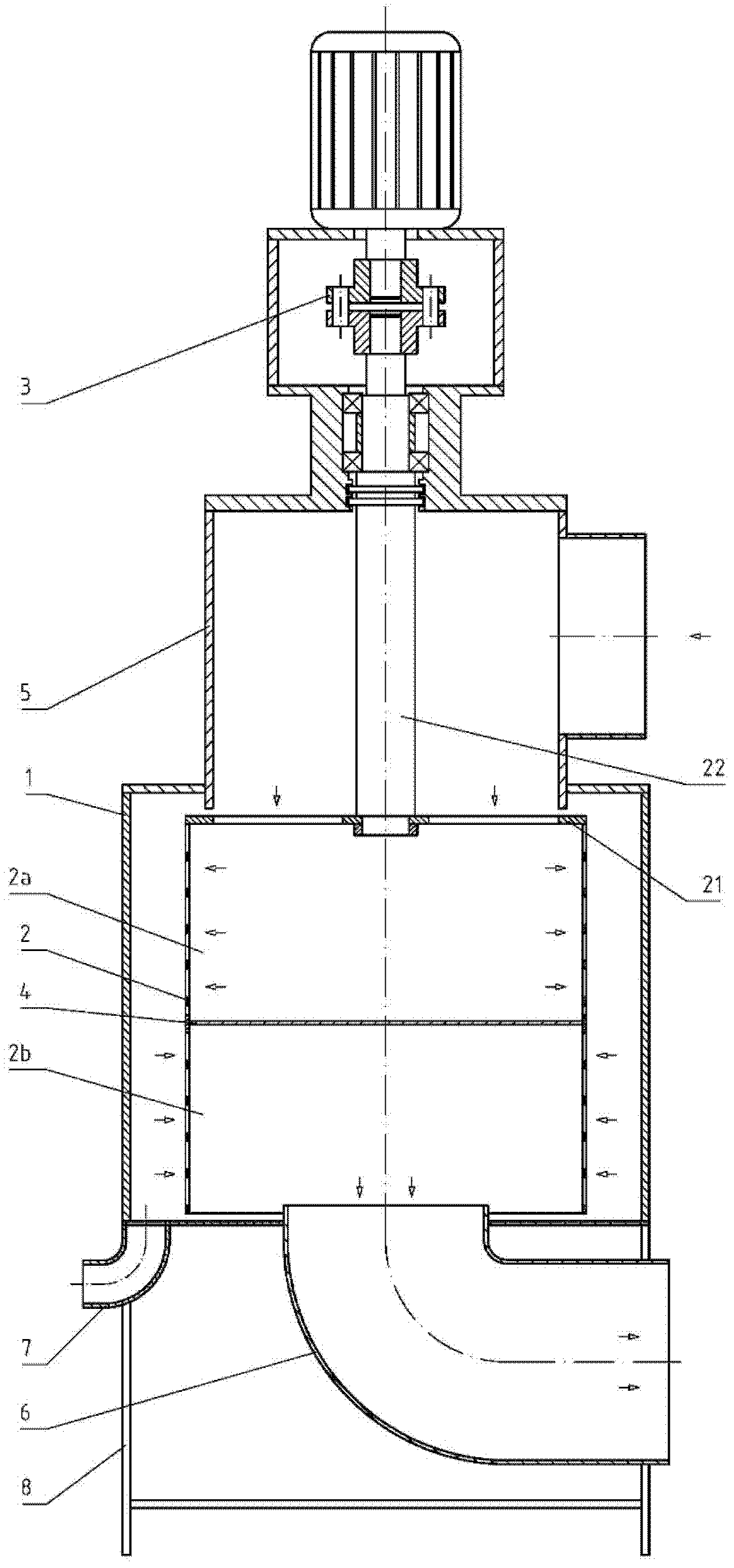
[0062] refer to figure 1 As shown, an active centrifugal gas-liquid separation device adopts a vertical layout scheme, mainly including a housing 1, a drum 2, a power unit 3, a partition plate 4, an air intake pipe 5, an exhaust pipe 6, and a liquid discharge pipe 7. Rack 8. The drum has a diameter of 1m and a rotating speed of 2500r / min. The shell 1 made of steel plate is set on the frame 8, and the shell 1 is provided with a drum 2. The drum 2 is made of a steel pipe, and the wall of the drum is provided with A large number of ventilation holes, the space inside the cylinder and the space outside the cylinder are connected through the ventilation holes; the drum 2 is connected to the power device 3 through the cylinder cover 21 and shaft 22 with ventilation holes, the power device 3 includes a motor and a coupling, and the drum 2 passes through The shaft 22 and the bearing are supported on the bearing seat, and are driven by the power unit 3 to rotate around its own axis. ...
Embodiment 2
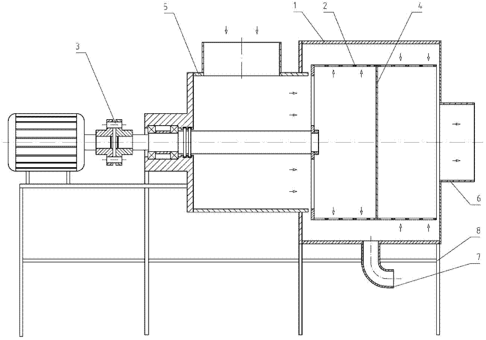
[0066] refer to figure 2 As shown, an active centrifugal gas-liquid separation device adopts a horizontal layout scheme, and the drain pipe 7 is arranged at the lowest part of the casing 1, and the rest is the same as that of the first embodiment.
Embodiment 3
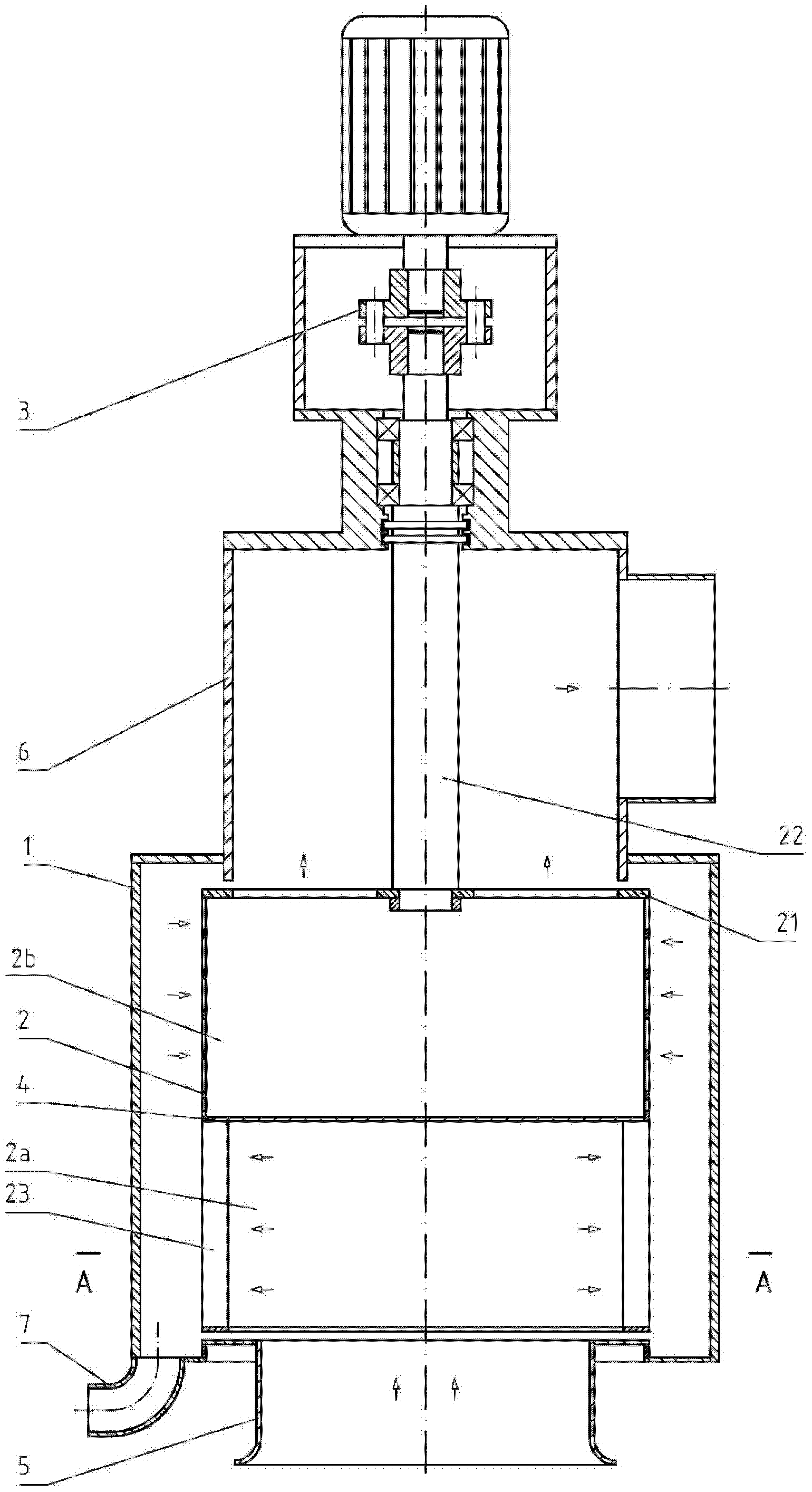
[0068] refer to image 3 , Figure 4 As shown, an active centrifugal gas-liquid separation device adopts a vertical layout scheme, the inlet pipe 5 is located at the lower end of the shell 1, the exhaust pipe 6 is located at the upper end of the shell 1, and the cylinder wall at the intake end of the drum 2 is provided with multiple A centrifugal blade 23, a plurality of centrifugal blades 23 together with the rotating drum 2 constitute a centrifugal turbine impeller, which can provide a certain wind pressure when the rotating drum 2 rotates to promote the flow of gas. Among the figures, ω is the rotating direction of the rotating drum 2. All the other are with embodiment 1.
PUM
 Abstract
Description
Claims
Application Information