Gas-solid separator of recirculating fluidized bed boiler and boiler comprising same

一种气固分离器、循环流化床的技术,应用在流化床燃烧设备、分离方法、弥散粒子分离等方向,能够解决锅炉启停慢、飞灰量大、增加维修费用等问题,达到延长使用寿命、提高综合能效、减少烟尘排放的效果

Active Publication Date: 2012-07-18
王森
View PDF5 Cites 15 Cited by
  • Summary
  • Abstract
  • Description
  • Claims
  • Application Information

AI Technical Summary

Problems solved by technology

[0008] At present, the most popular circulating fluidized bed separator with the highest share in the international and domestic markets is a high-temperature cyclone separator made of refractory materials. Its main advantage is high separation efficiency, and its main disadvantages are bulky size and high wind speed at the tangential inlet of the separator. , high resistance, high power consumption of induced draft fan, high-speed flow of gas-solid two-phase toward the silo air flow reversely entrains a large amount of fly ash, and the original emission concentration of smoke and dust is high. The separator needs inner lining and outer heat insulation. The large amount of high-temperature grinding materials not only increases the cost of raw materials and manufacturing and installation of the separator, but also increases the thermal inertia, which is easy to coke at high temperature and slows down the boiler start-up and shutdown.
Some boilers use water-cooled or steam-cooled cyclone separators. Although the wear-resistant and high-temperature resistant materials are reduced, the problem of large thermal inertia is solved, the boiler does not coke, and the start and stop are fast, but there are also high wind speeds, large resistance, and induced draft fans. Power consumption is high, and the separation efficiency and stability are lower than those of cyclone separators made of wear-resistant high-temperature materials. In addition, its manufacturing process is complicated, resulting in high prices and low market share.
[0009] Although the gas-solid separation in the circulating fluidized bed boiler disclosed in the invention patent with the application number 200910308160.1 has many advantages compared with the high-temperature cyclone separator, such as low flow resistance, saving the power consumption of the induced draft fan, and saving Wear-resistant high-temperature materials, etc., but there are still many defects in its structure, such as the entrance and exit of the turning channel are unimpeded, first, the inertial separation performance is poor, and second, the front and rear walls of the silo have no water-cooled walls, which affects the quality and life of the furnace wall and increases maintenance costs; Third, the application range of this structure is small, and it is not suitable for large-scale development

Method used


Image

  • Gas-solid separator of recirculating fluidized bed boiler and boiler comprising same
  • Gas-solid separator of recirculating fluidized bed boiler and boiler comprising same
  • Gas-solid separator of recirculating fluidized bed boiler and boiler comprising same

Examples


Embodiment 1

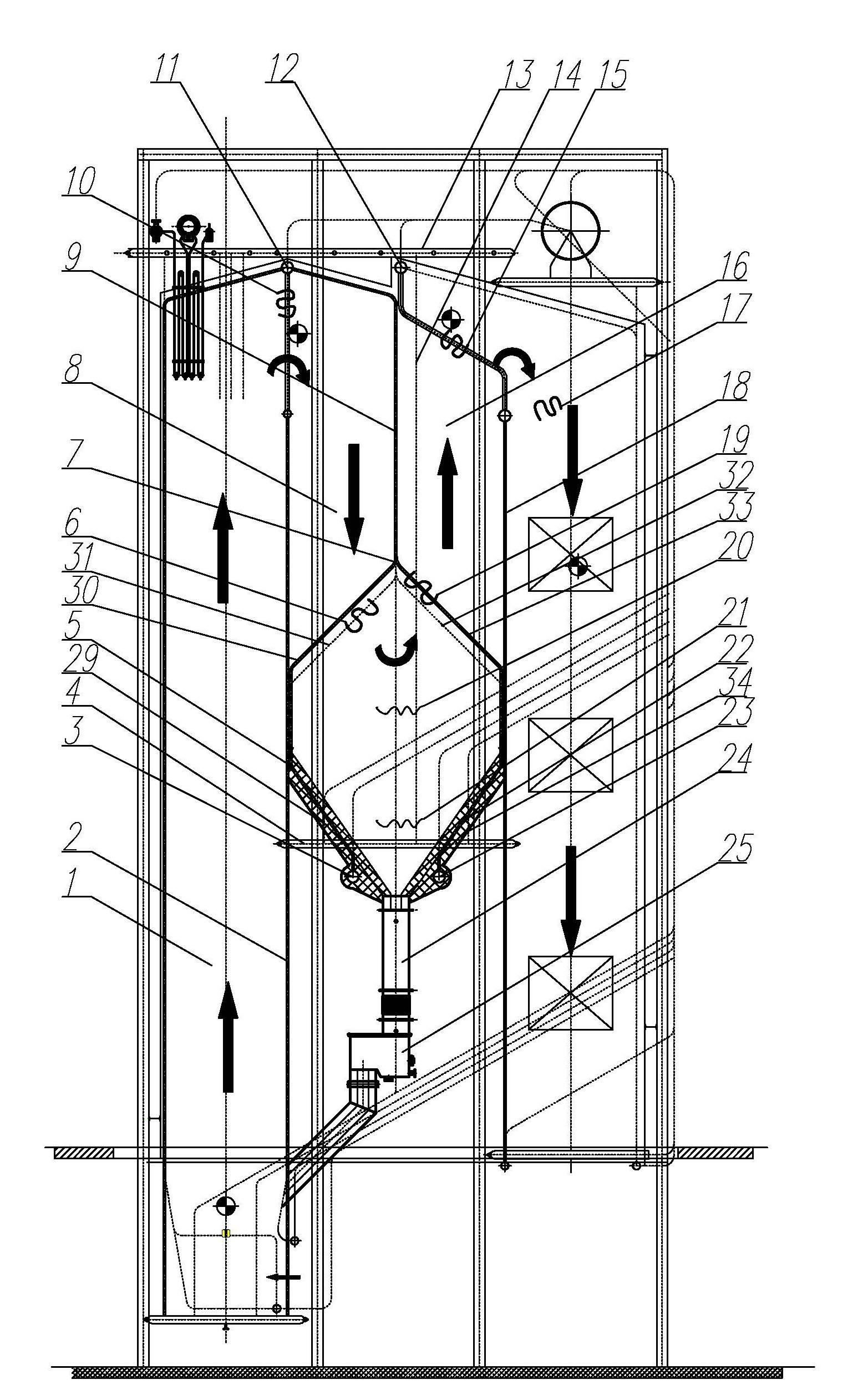
[0049] Embodiment 1: In this embodiment, the gas-solid separator of the circulating fluidized bed boiler is introduced together with the circulating fluidized bed boiler using the gas-solid separator. In this embodiment, only the gas-solid separation of the boiler is involved. The structure of the boiler and other structures of the boiler can adopt the conventional boiler structure or the new boiler structure, and the other parts of the boiler will not be described in detail. Please refer to the attached figure 1, in this embodiment, it mainly includes four major parts, namely boiler furnace 1, gas-solid separator, shaft 17 and return device (return device described in this embodiment is return valve 25), gas-solid separator It is arranged at the rear of the furnace 1 and the front of the shaft 17. In this embodiment, the gas-solid separator includes a downgoing flue 8 and an upgoing flue 16 separated from front to back by the lower and upper turning membrane screen 9 leading...

Embodiment 2

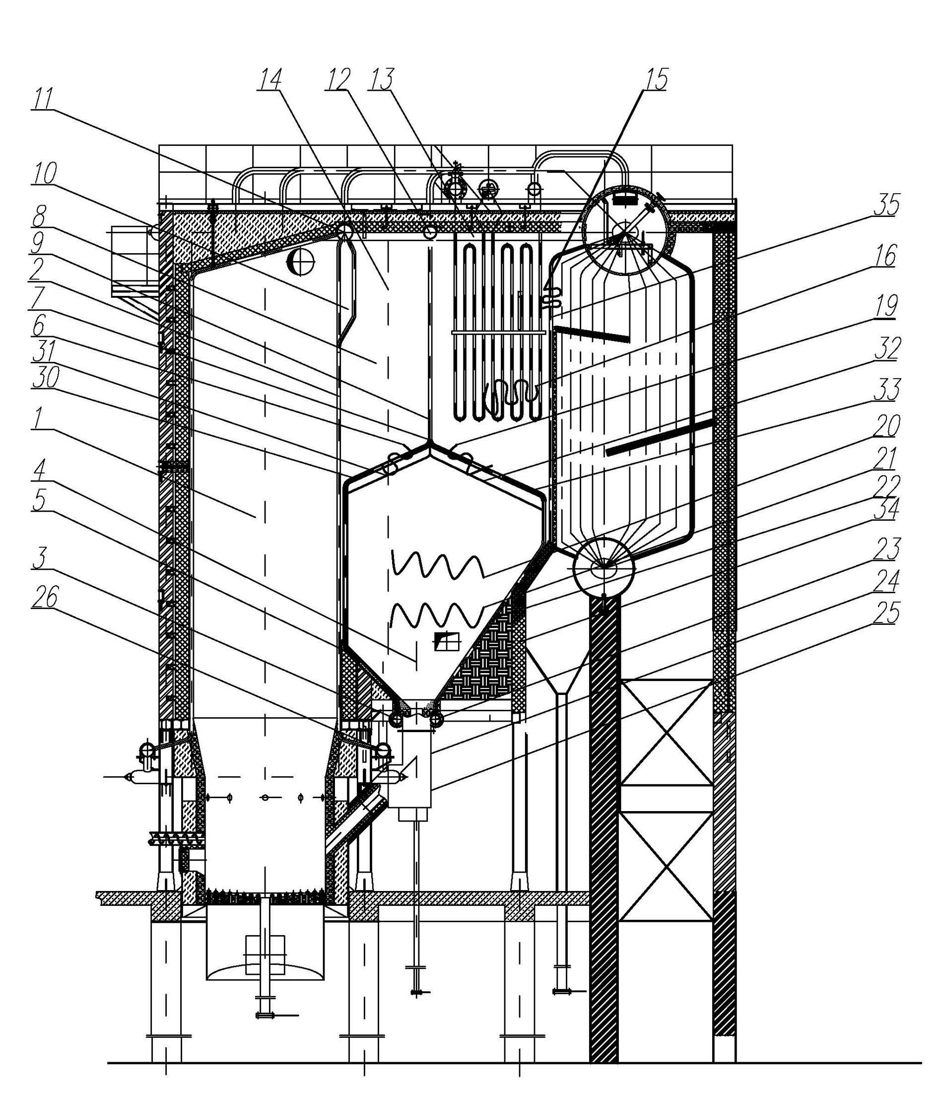
[0052] Example 2: See attached figure 2 In this embodiment, the tube bundles of the flue gas inlet 6 and the flue gas outlet 19 of the turning passage can be asymmetrical or symmetrical, and the front and rear wall tubes of the silo can be asymmetrical or symmetrical. The basic structure of this embodiment is similar to Embodiment 1. The main difference between this embodiment and Embodiment 1 is that the boiler in this embodiment is a horizontal double-drum boiler, and the shaft is at the lower end of the convection tube bundle, which is less than or equal to half shaft. The working process of the separator in this embodiment is the same as in Embodiment 1.

[0053] The flow velocity of the dense-phase zone and the dilute-phase zone of the boiler in this embodiment: higher than that of the fluidized bed boiler and lower than that of the low circulation rate fluidized bed boiler, the average flow velocity of the gas-solid separator downflow flue and upflow flue is 3m / s to 4m...

Embodiment 3

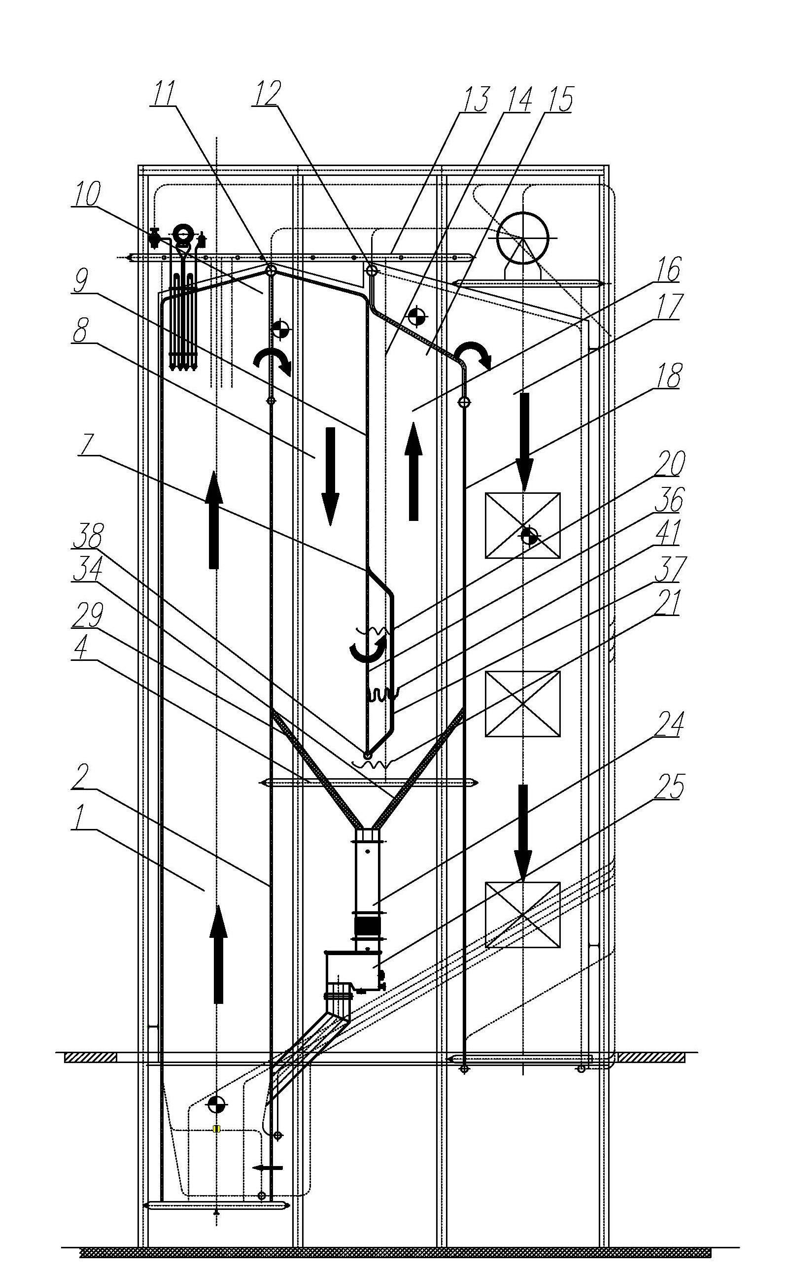
[0054] Example 3: See attached image 3 , the basic structure of this embodiment is the same as that of Embodiment 1. The difference between this embodiment and Embodiment 1 is that the front row of tube bundles 36 and the rear row of tube bundles 37 are formed on the lower turning channel of the membrane screen bifurcation 7 or Add tube rows and bundles backwards. The specific structure is: the lower part of the membrane screen bifurcation 7 is divided into two rows (or three to five rows of tube bundles are arranged in sequence backwards, and the longitudinal spacing and number of tube rows are determined based on the selection of the flue gas flow rate) , the lower end of the front tube bundle 36 communicates with the upper part of the lower horizontal header 38 of the tube bundle, and the rear tube bundle 37 (all tube bundles from the front tube bundle 36 are defined as the rear tube bundle) is a distance away from the front tube bundle 36, and its lower end is connected t...


PUM


Abstract

A gas-solid separator of a recirculating fluidized bed boiler comprises a downward flue and an upward flue which are separated from front to back by a membrane-type guided flue gas downward and upward turning screen; the downward flue and the upward flue are communicated with each other through a swerving passageway and a feed bin which is hermetically installed below the downward flue and the upward flue; a flue gas inlet is arranged at the front upper part of the gas-solid separator and a flue gas outlet is arranged at the back upper part of the gas-solid separator; four walls of the gas-solid separator are all water cooled walls which are integrated with the boiler; the gas-solid separator further comprises a flow equalizing and separating tube bundle and an abrasion-proof communication pipe which are located on the swerving passageway; the upper end of the flow equalizing and separating tube bundle on the swerving passageway is communicated with a lower cross collecting tank of the membrane-type guided flue gas downward and upward turning screen, and the lower end of the flow equalizing and separating tube bundle on the swerving passageway is communicated with a cross collecting tank of the feed bin; and the upper end of the abrasion-proof communication pipe on the swerving passageway is communicated with the lower cross collecting tank of the membrane-type screen, and the lower end of the abrasion-proof communication pipe on the swerving passageway is communicated with a cross collecting tank of the communication pipe. In the case of circulation at low ratio, inertia gravity is used for single stage separation, and in the case of circulation at high ratio, when the speed of the smoke in the upward flue is high, low-temperature cyclone separation can be combined with inertia gravity separation for double-stage separation.

Description

[0001] technical field [0002] The invention discloses a gas-solid separator, which is the core component of a circulating fluidized bed boiler. The gas-solid separation of the circulating fluidized bed boiler does not require any special devices and separation elements. And the inertial gravity separator naturally formed by the heating surface space integrated with the boiler body. In particular, it involves the new product design of the gas-solid separator for circulating fluidized bed boilers and the energy saving and emission reduction transformation of various circulating fluidized bed boilers and layer fired chain boilers. Background technique [0003] Circulating fluidized bed boiler combustion technology is widely recognized as a "clean" combustion technology with the most development prospects due to its advantages such as wide fuel adaptability, high combustion efficiency, low nitrogen oxide emissions, high-efficiency desulfurization, and good load regulation ...

Claims


Application Information

Patent Timeline
Patent Type & Authority Applications(China)
IPC IPC(8): F23C10/18
CPCF23J2900/15025F23J2217/20B01D45/12F23C10/10F23J15/022
Inventor 王森
Owner 王森
Why Eureka
Try Eureka