
Apparatus for generating mixed gas of hydrogen and oxygen, and internal combustion engine using the same

A technology of gas generating device and internal combustion engine, which is applied to internal combustion piston engines, combustion engines, combustion air/combustion-air treatment, etc., can solve problems such as technologies that do not have combustion technology, and achieve the effect of reducing emissions

Active Publication Date: 2012-07-18
LEGARSI +1
View PDF10 Cites 5 Cited by
  • Summary
  • Abstract
  • Description
  • Claims
  • Application Information

AI Technical Summary

Problems solved by technology

[0003] However, at the current level of technology, it is impossible to switch to technology that does not have a combustion process, and there is always a technical field where the combustion process of fossil fuels is inevitable.

Method used


Image

  • Apparatus for generating mixed gas of hydrogen and oxygen, and internal combustion engine using the same
  • Apparatus for generating mixed gas of hydrogen and oxygen, and internal combustion engine using the same
  • Apparatus for generating mixed gas of hydrogen and oxygen, and internal combustion engine using the same

Examples


Embodiment 1

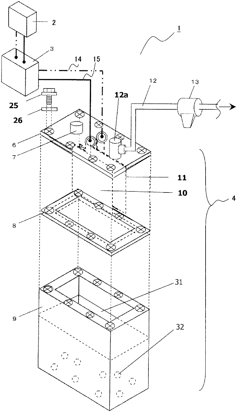
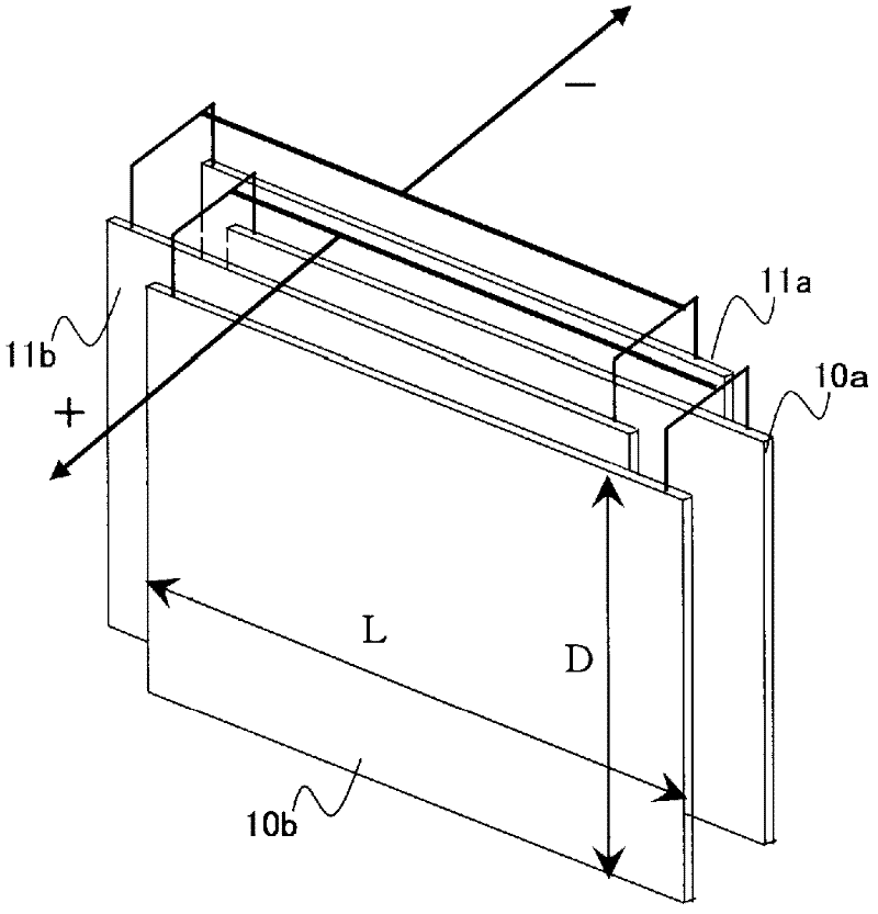
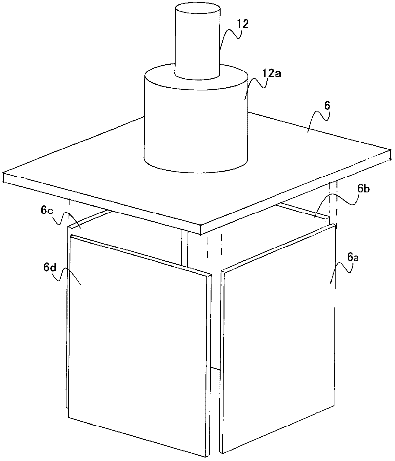
[0024] refer to Figure 1 ~ Figure 4 , the oxyhydrogen gas generator 1 of the present invention will be described. figure 1 It is a figure which shows the oxyhydrogen gas generator of this invention. Figure 2A It is a figure showing an example of the electrode structure of the oxyhydrogen gas generator of the present invention, Figure 2B It is a figure which shows the gas collection part of the oxyhydrogen gas generator of this invention. in addition, image 3 It is a system diagram of the oxyhydrogen gas generator of Embodiment 1 of the present invention. Figure 4 Represents the control flow diagram of the converter.

[0025] The oxyhydrogen gas generator 1 includes a power source 2 , an inverter 3 , an electrolytic cell 4 , and an oxyhydrogen gas supply pipe 12 .

[0026] The power supply 2 can be selected without particular limitation as long as it can supply electric power to the electrolytic cell 4 . For example, power source 2 may be a 24 volt power source. The...

Embodiment 2

[0054] refer to Figure 5 , Figure 6 , Figure 7 , the oxyhydrogen gas generator 1 of the present invention as another embodiment will be described. Embodiment 1 is basically the same as Embodiment 2, but the difference lies in the point that the state of the internal combustion engine 20 is included in the control of the inverter 3 . Figure 5 It is a system diagram of the oxyhydrogen gas generator 1 according to the second embodiment of the present invention. Figure 6 A control flow diagram of the inverter in this case is shown. The oxyhydrogen gas generator 1 other than the inside of the inverter 3 is the same as that of the first embodiment. Hereinafter, parts that are different from those in Embodiment 1 will be described, and descriptions of parts that are the same as in Embodiment 1 will be omitted.

[0055] Such as Figure 6 As shown, the internal combustion engine has an output shaft, and the rotational speed of the output shaft is detected by a rotation senso...


PUM


Abstract

Provided is an apparatus for generating a hydrogen-oxygen gas which generates hydrogen gas with a low current and with generation of a small amount of water vapor. The apparatus for generating a hydrogen-oxygen gas comprises: a power supply; an inverter electrically connected to the power supply; and an electrolytic bath which is electrically connected to the inverter and which contains nanowater and a positive electrode and a negative electrode immersed in the nanowater. It is therefore possible for the apparatus to be driven with a low current and for the amount of water vapor generated to be reduced.

Description

technical field [0001] The present invention relates to a device for generating a mixed gas of hydrogen and oxygen (hereinafter referred to as "oxygen gas") as a Brownian gas, and an internal combustion engine using the device. Background technique [0002] In recent years, technological development emphasizing environmental consideration has been carried out in various technical fields. Especially in the field of technology that utilizes the combustion of fossil fuels such as internal combustion engines, it is actively developing to reduce CO 2 emission-oriented technology. For example, CO reduction by switching to technologies without combustion processes 2 emissions is one way. Examples include electrically driven cars using various types of power generation and storage technologies, including hybrid cars that have been put into practical use. [0003] However, at the current technical level, it is impossible to switch to a technology that does not have a combustion p...

Claims


Application Information

Patent Timeline
Patent Type & Authority Applications(China)
IPC IPC(8): C25B1/04C25B9/00F02M25/12
CPCF02M25/12F02M27/04C25B9/00F02D19/0671F02D19/0644Y02T10/36Y02T10/121C25B1/04Y02E60/366Y02E60/36Y02T10/12Y02T10/30C25B1/044C25B9/67
Inventor 柳原伸光今村充生
Owner LEGARSI
Learn More