
Dedusting system for flue gas ammonia desulphurization and application method of dedusting system

A dust removal system, ammonia desulfurization technology, applied in separation methods, chemical instruments and methods, dispersed particle separation, etc., can solve the problems of ammonia desulfurization users can not run long-term, stable operation, unstable operation, wear and tear of the piping system, etc. Solve the problem of up-to-standard emission of smoke and dust, ensure long-term stable operation, and improve the effect of quality

Active Publication Date: 2012-07-25
兖矿科技有限公司
View PDF2 Cites 2 Cited by
  • Summary
  • Abstract
  • Description
  • Claims
  • Application Information

AI Technical Summary

Problems solved by technology

However, since the existing ammonia desulfurization process does not have effective and reliable ash removal facilities, and the flue gas at the outlet of the dust removal equipment (electrostatic precipitator or bag filter) still contains a relatively high concentration of dust, resulting in ammonia desulfurization cycle system Large dust content, wear and blockage of pump valves, nozzles, and piping systems make most users of ammonia desulfurization unable to operate stably for a long time
[0003] The existing ammonia desulfurization process system generally uses a filter tank or a filter to filter the ash from the ammonium sulfate solution, which is unstable in operation and poor in effect

Method used


Image

  • Dedusting system for flue gas ammonia desulphurization and application method of dedusting system
  • Dedusting system for flue gas ammonia desulphurization and application method of dedusting system

Examples


Embodiment 1

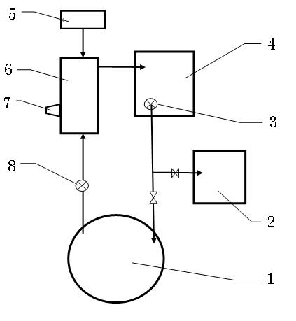
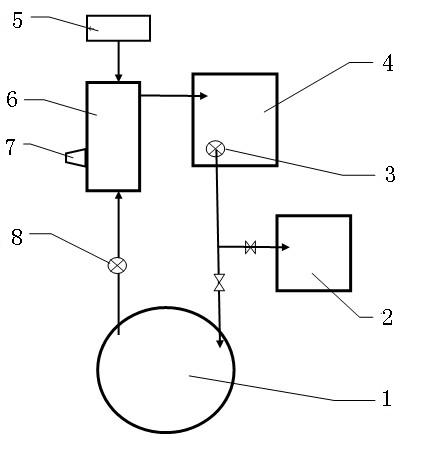
[0026] The dedusting system includes a desulfurization tower 1, a slurry pump 8, a horizontal screw centrifuge 6, a clear liquid pool 4, a clear liquid pump 3, an electric control system 5, and an evaporation concentration system 2. The above desulfurization tower 1, slurry pump 8, horizontal The horizontal screw centrifuge 6 and the clear liquid pump 3 located in the clear liquid pool 4 are connected in series through pipelines to form a closed loop; the horizontal screw centrifuge 6 is connected with an electric control system 5, which controls the horizontal In order to start and run the horizontal screw centrifuge 6, the horizontal screw centrifuge 6 is also provided with a mud outlet 7, through which the sludge deposited in the horizontal screw centrifuge 6 is discharged; the clear liquid pump 3 and An evaporation and concentration system 2 is connected to the pipeline between the desulfurization towers 1 .

[0027] The main principle of flue gas ammonia desulfurization i...

Embodiment 2

[0032] The dedusting system includes a desulfurization tower 1, a slurry pump 8, a horizontal screw centrifuge 6, a clear liquid pool 4, a clear liquid pump 3, an electric control system 5, and an evaporation concentration system 2. The above desulfurization tower 1, slurry pump 8, horizontal The type screw centrifuge 6 and the clear liquid pump 3 located in the clear liquid pool 4 are connected in series through pipelines to form a closed loop; the horizontal screw centrifuge 6 is connected with an electric control system 5, and the horizontal screw centrifuge 6 is There is also a mud outlet 7; the pipeline between the clear liquid pump 3 and the desulfurization tower 1 is connected with an evaporation concentration system 2.

[0033] The main principle of flue gas ammonia desulfurization is to combine ammonia water with SO in boiler flue gas 2 In the desulfurization tower, the reaction produces (NH 4 ) 2 SO 3 , (NH 4 ) 2 SO 3 with O 2 combined to form a more stable (N...

Embodiment 3

[0037] The dedusting system includes a desulfurization tower 1, a slurry pump 8, a horizontal screw centrifuge 6, a clear liquid pool 4, a clear liquid pump 3, an electric control system 5, and an evaporation concentration system 2. The above desulfurization tower 1, slurry pump 8, horizontal The type screw centrifuge 6 and the clear liquid pump 3 located in the clear liquid pool 4 are connected in series through pipelines to form a closed loop; the horizontal screw centrifuge 6 is connected with an electric control system 5, and the horizontal screw centrifuge 6 is There is also a mud outlet 7; the pipeline between the clear liquid pump 3 and the desulfurization tower 1 is connected with an evaporation concentration system 2.

[0038] The main principle of flue gas ammonia desulfurization is to combine ammonia water with SO in boiler flue gas 2 In the desulfurization tower, the reaction produces (NH 4 ) 2 SO 3 , (NH 4 ) 2 SO 3 with O 2 combined to form a more stable (N...


PUM


Abstract

The invention relates to a dedusting system for boiler flue gas desulfurization, in particular to a dedusting system for flue gas ammonia desulfurization. The invention also relates to a method for applying the dedusting system in an ammonia desulfurization system. The dedusting system comprises a desulfurizing tower, a slurry pump, a centrifugal machine, a clear liquid pool, a clear liquid pump, an electric control system and an evaporation concentration system, wherein the desulfurizing tower, the slurry pump, the centrifugal machine and the clear liquid pump positioned in the clear liquid pool are sequentially connected in series through a pipeline to form a closed loop, the centrifugal machine is connected with the electric control system, the centrifugal machine is also provided with a mud outlet, and the pipeline between the clear liquid pump and the desulfurizing tower is connected with the evaporation concentration system. By the dedusting system and an application method of the dedusting system, provided by the invention, the problems that in the existing ammonia wet-type desulfurization system, due to desulfurizing circulating solution contains the large ash content, a pump valve, a nozzle, a piping system and the like are seriously worn and blocked, and the like can be effectively solved, so that the ammonia wet-type desulfurization system can safely and stably operate, and the sulfur dioxide emission can reach the standard for a long time.

Description

technical field [0001] The invention relates to a dust removal system for boiler flue gas desulfurization, in particular to a dust removal system for ammonia desulfurization of flue gas, and also relates to a method for applying the dust removal system to an ammonia desulfurization system. Background technique [0002] Although the ammonia desulfurization process started late, it is relatively mature, and there are more than 60 desulfurization devices put into operation in China. Ammonia desulfurization can easily achieve a desulfurization efficiency of more than 98%. The "three wastes" are produced in a very small amount and are easy to handle. The by-product ammonium sulfate can be used to produce fertilizers, with high utilization value, so the overall cost is very low, and the social and economic benefits are obvious. , is a green process in line with the national low-carbon circular economy. However, because the existing ammonia desulfurization process does not have e...

Claims


Application Information

Patent Timeline
IPC IPC(8): B01D53/78B01D53/50B01D53/96
Inventor 刘学冰郝敬武苗因德付丛伟刘喆徐秀国
Owner 兖矿科技有限公司
Learn More