Electric transmission and transformation equipment contact luminous temperature sensing cap system

A power transmission and transformation equipment, light-emitting technology, used in signal transmission systems, thermometers, thermometers, etc., which are directly sensitive to heat-sensitive electrical/magnetic components, can solve the problem of unintuitive, power transmission and transformation equipment contacts can not be remotely known, transmission Problems such as outdated temperature measurement methods of substation equipment, to achieve the effect of simple wiring, increased use range, and low power consumption

Inactive Publication Date: 2012-07-25
国网山东济南市历城区供电公司 +1
View PDF6 Cites 7 Cited by
  • Summary
  • Abstract
  • Description
  • Claims
  • Application Information

AI Technical Summary

Problems solved by technology

[0021] The technical problem to be solved by the present invention is to provide a light-emitting sensor for the contact points of power transmission and transformation equipment in view of the fact that the temperature measurement method of the existing power transmission and transformation equipment is too old and not intuitive, and the overheating of the contacts of the power transmission and transformation equipment cannot be remotely known. The temperature cap system has the advantages of reasonable design and intuitive monitoring results

Method used


Image

  • Electric transmission and transformation equipment contact luminous temperature sensing cap system
  • Electric transmission and transformation equipment contact luminous temperature sensing cap system
  • Electric transmission and transformation equipment contact luminous temperature sensing cap system

Examples


Embodiment 1

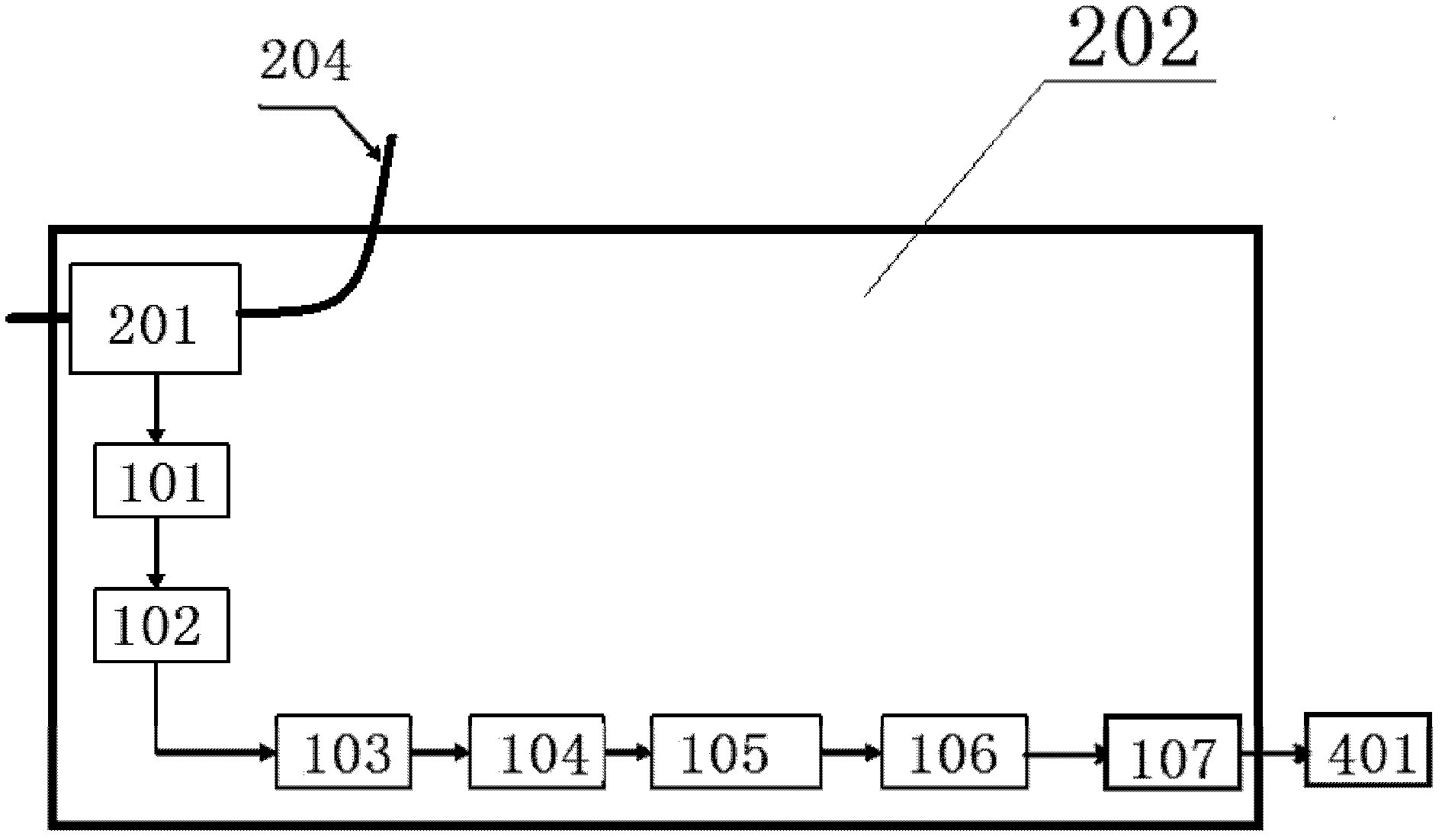
[0122] Example 1: figure 1 , Shows the circuit diagram of the high-voltage self-contained power supply device.

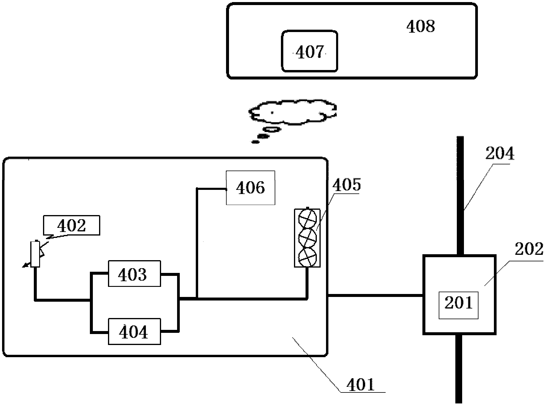
[0123] CT directly induces the AC voltage from the primary current, passes the smoothing reactance 101 and uses the full-wave rectifier bridge 102 to convert, obtains a relatively stable DC voltage on the stabilized capacitor 103, and then passes the voltage protection circuit 104, filter circuit 105 and The DC-DC module 106 and the current-limiting resistor 107 are converted into a 3.3V power supply for the electronic circuit in the light-emitting temperature sensing cap 401 of the contact of the power transmission and transformation equipment. When the CT is deeply saturated, both the induced voltage and the induced current rise significantly. After the smoothing reactance is added to the position between the CT and the full-wave rectifier bridge 102, it can share most of the high voltage induced by the CT and limit the current of the CT Output. The voltage protecti...


PUM


Abstract

The invention discloses an electric transmission and transformation equipment contact luminous temperature sensing cap system. The system comprises a power supply device, an electric transmission and transformation equipment contact luminous temperature sensing cap and a monitoring center; the power supply device is electrically connected with the electric transmission and transformation equipment contact luminous temperature sensing cap; the electric transmission and transformation equipment contact luminous temperature sensing cap comprises a wireless transmitting module, and the wireless transmitting module is communicated with a wireless receiving module of the monitoring center through a network; and the electric transmission and transformation equipment contact luminous temperature sensing cap also comprises a fixed and shielded part and a temperature measuring part, wherein the temperature measuring part is arranged in the fixed and shielded part, and a luminous early warning device is arranged in the temperature measuring part. The invention has the advantage that the system is affected little by the outside because independent circuits are used for monitoring the temperature. Different color lamps are displayed according to different temperature control circuits, and the system can accurately monitor temperature, and has stable performances and an obvious practical effect.

Description

Technical field [0001] The invention relates to a contact temperature sensing system for power transmission and transformation equipment of a power system, in particular to a contact light-emitting temperature sensing cap system for power transmission and transformation equipment. Background technique [0002] With the development of my country's economy and the continuous improvement of people's living standards, the power load supplied by power supply companies has also increased rapidly, which puts forward higher requirements for how power supply companies can achieve safe and reliable power supply. [0003] In the actual operation of the power grid, there are countless line connection points between the power transmission and transformation equipment; with the increase of electricity load, the number of heating points of the line connection contacts is increasing, and the total number of heating points is increasing year by year. Line tripping accidents caused by overheating of...

Claims


Application Information

Patent Timeline
Patent Type & Authority Applications(China)
IPC IPC(8): G01K7/22G01K7/04G01K7/01G08C17/02
Inventor 常维华王军勃王玉玮石滨许林高阳郭强
Owner 国网山东济南市历城区供电公司
Why Eureka
Try Eureka