
Environmental safety monitoring system

A monitoring system and environmental safety technology, applied in the direction of comprehensive factory control, comprehensive factory control, electrical program control, etc., can solve the problems of waste of electricity and other resources, casualties, waste of manpower, etc., to achieve large network capacity, high security, low cost effect

Inactive Publication Date: 2012-07-25
DALIAN A NON TECH
View PDF7 Cites 6 Cited by
  • Summary
  • Abstract
  • Description
  • Claims
  • Application Information

AI Technical Summary

Problems solved by technology

[0003] 1. Manually starting the emergency treatment equipment such as fans delays the time to evacuate the scene, which may lead to safety accidents such as casualties;
[0004] 2. The emergency information cannot be sent to the relevant rescue department at the first time, so that only self-rescue can be carried out, and the corresponding external rescue cannot be obtained within the best rescue time;
[0005] 3. After all the personnel are evacuated, it is impossible to grasp the gas concentration value at the scene, and it is impossible to judge whether the scene is safe, so that it is impossible to return to the scene in time; entering too early is still unsafe, and entering too late will cause a waste of manpower on the one hand, and on the other hand On the one hand, the operation of fans and other equipment cannot be stopped in time, resulting in waste of resources such as electricity
Compared with the fixed type, although the handheld device has the advantage of being flexible and convenient to use, its biggest problem is that it cannot guarantee the safety of the inspectors. Call for help and cause safety accidents; in addition, special personnel are required to be responsible for inspections, which not only causes waste of human resources, but also cannot monitor the on-site air in real time.

Method used


Image

  • Environmental safety monitoring system
  • Environmental safety monitoring system

Examples


Embodiment Construction

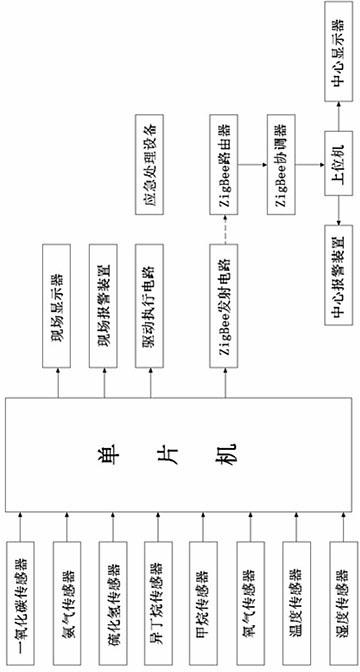
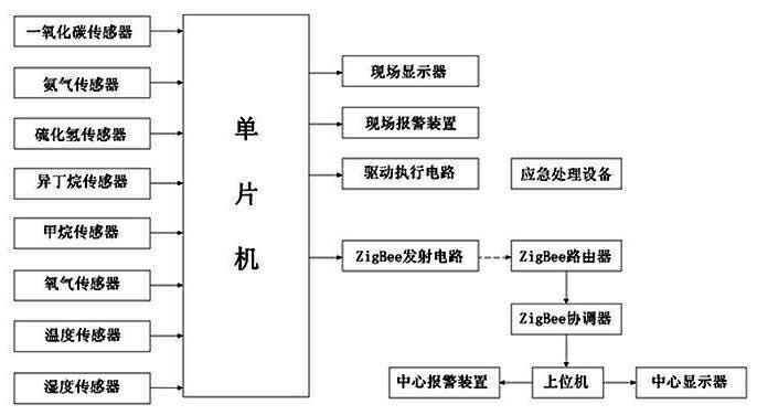
[0011] The specific implementation manner of the present invention will be described below with reference to the accompanying drawings. Such as figure 1 Shown: be provided with the same carbon monoxide sensor, ammonia sensor, hydrogen sulfide sensor, isobutane sensor, temperature sensor, humidity sensor, methane sensor and oxygen sensor identical with prior art, described carbon monoxide sensor, ammonia sensor, hydrogen sulfide The output of sensor, isobutane sensor, temperature sensor, humidity sensor, methane sensor and oxygen sensor is connected with single-chip microcomputer, and the difference of prior art is that the output of single-chip microcomputer is connected with ZigBee transmitting circuit, and the output terminal of single-chip microcomputer is also connected. There are on-site alarm device, on-site display and drive execution circuit connected, and the output of the drive execution circuit is connected with the emergency treatment equipment; a ZigBee router is ...


PUM


Abstract

The invention discloses an environmental safety monitoring system with the advantages that the cost is low, the safety is high, the field environment can be remotely monitored in real time, and emergency processing equipment such as warners, fans and the like are started in time. The environmental safety monitoring system is provided with a carbon monoxide sensor, an ammonia gas sensor, a hydrogen sulfide sensor, an iso-butane sensor, a temperature sensor, a humidity sensor, a methane sensor and an oxygen gas sensor, wherein the outputs of the sensors are connected with a single chip microcomputer, the output of the single chip microcomputer is connected with a ZigBee transmitting circuit, the output end of the single chip microcomputer is also connected with a field warning device, a field display and a driving executing circuit, and the output of the driving executing circuit is connected with emergency processing equipment. The environmental safety monitoring system is provided with a ZigBee router corresponding to the ZigBee transmitting circuit and a ZigBee coordinator corresponding to the ZigBee router, the output of the ZigBee coordinator is connected with an upper computer, and the upper computer is connected with a center warning device and a center display.

Description

technical field [0001] The invention relates to an environmental safety monitoring system, in particular to an environmental safety monitoring system with low cost and high safety, which can remotely monitor the field environment in real time and start alarms and emergency treatment equipment such as fans in time. Background technique [0002] At present, environmental security monitoring systems are mostly handheld or fixed. The fixed type is to install gas sensors, single-chip microcomputers, alarms and other detection equipment in the environment (cabin, workshop, etc.) that need to be detected. When the gas concentration detected by the sensor is greater than the set critical value, the alarm device is activated. Remind the on-site workers to evacuate, and at the same time manually turn on the emergency treatment equipment such as fans for ventilation. Although fixed equipment can detect excessive gas concentration in time and issue an alarm on the spot, there are the f...

Claims


Application Information

Patent Timeline
IPC IPC(8): G05B19/418
CPCY02P90/02
Inventor 张国振王凯
Owner DALIAN A NON TECH
Learn More