Ultra wide band four-tape circularly polarized antenna

A circularly polarized antenna, ultra-wideband technology, applied in the antenna grounding device, radiating element structure and other directions, can solve the problem of the inability to determine the feeding position by numerical methods, the difficulty of realizing the multi-band circular polarization function of the antenna, the cost and debugging of the antenna. Increase the difficulty and other problems, to achieve the effect of improving impedance matching characteristics, reducing design costs, and designing simple and flexible

Inactive Publication Date: 2012-07-25
XIDIAN UNIV
View PDF4 Cites 16 Cited by
  • Summary
  • Abstract
  • Description
  • Claims
  • Application Information

AI Technical Summary

Problems solved by technology

In the research, the monopole antenna structure is mostly used to realize the ultra-wideband characteristics of the antenna. The method is simple and easy to implement, but the polarization mode of this antenna is generally linear polarization, and it is difficult to realize the multi-band circular polarization function of the antenna.
Some researchers use multiple orthogonal feed sources or multi-layer dielectric substrates in the antenna to achieve multi-band circular polarization characteristics. Although this structure has good circular polarization performance, it is difficult for the antenna to achieve ultra-wideband characteristics, and its own Increased antenna complexity and coupling between different frequency bands and polarizations, resulting in increased antenna cost and debugging difficulty
There are also some studies that use multi-band circularly polarized antennas composed of curved microstrip lines. This kind of structure is irregular, and its feeding position cannot be determined by numerical methods. It is not common in practice, and the structure is relatively complicated, mainly relying on Practical engineering experience to achieve its purpose, subject to certain restrictions in practical application
Due to the shortcomings of the above methods, their application in the field of mobile terminals and satellite communications is limited.

Method used


Image

  • Ultra wide band four-tape circularly polarized antenna
  • Ultra wide band four-tape circularly polarized antenna
  • Ultra wide band four-tape circularly polarized antenna

Examples


Embodiment 1

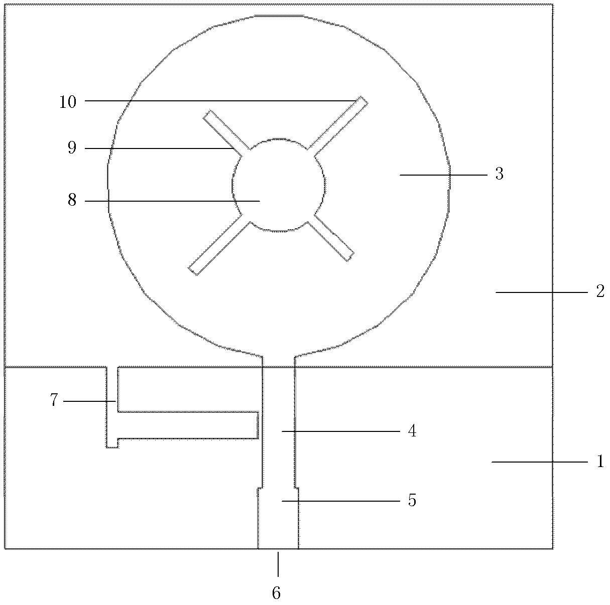
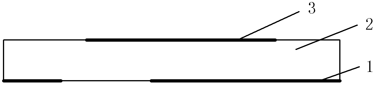
[0037] see figure 1 and figure 2 , the ultra-broadband four-band circularly polarized antenna of the present invention includes: a metal floor 1, a square dielectric substrate 2, a radiation patch 3, a feeding branch 4, a matching branch 5 and a microstrip line feed 6, and the radiation patch 3 Electrically connect to the microstrip line feed source 6 through the feeding stub 4 and the matching stub 5. The radiation patch 3, the feeding stub 4 and the matching stub 5 are all printed on the front surface of the dielectric substrate 2 in an axisymmetric manner structure; a polarization hole 8 is etched on the central position of the radiation patch 3, and the edge of the polarization hole 8 is provided with two mutually orthogonal rectangular slits 9 and 10, and the intersection point of the two slits and the center of the polarization hole 8 The points coincide; the microstrip line feed 6 is placed on the edge of the dielectric substrate 2 .

[0038] The shape of the polariz...

Embodiment 2

[0044] see image 3 , the radiation unit 3 of the ultra-broadband four-band circularly polarized antenna in this embodiment is an elliptical patch, the polarization hole 8 etched on the radiation unit 3 adopts an elliptical structure, and the major axis radius of the elliptical radiation patch 3 is 8mm , the minor axis radius is 4mm, the major axis radius of the radius of the oval polarization hole 8 is 3mm, the minor axis radius is 1.5mm, the length of the rectangular slit 9 is 8mm, the width is 0.1mm, the length of the rectangular slit 10 is 10mm, The width is 0.1 mm, the dielectric constant of the dielectric substrate 2 is 1, and the rest of the structure is the same as that of Embodiment 1.

Embodiment 3

[0046] see Figure 4 , the radiation unit 3 of the ultra-broadband four-band circularly polarized antenna in this embodiment is a rectangular patch, the polarization hole 8 etched on the radiation unit 3 adopts a square structure, and the length of the rectangular radiation patch 3 is 18mm, and the width is 9mm , the side length of the square polarization hole 8 is 2.3 mm, the length of the rectangular slot 9 is 12 mm, and the width is 1 mm, the length of the rectangular slot 10 is 14 mm, and the width is 1 mm, the dielectric constant of the dielectric substrate 2 is 10, and the rest of the structure is the same as Same as in Example 1.

[0047] The above are three specific examples of the present invention and do not constitute any limitation to the present invention.


PUM


Abstract

The invention discloses an ultra wide band four-tape circularly polarized antenna which comprises a metal floor (1), a dielectric substrate (2), a radiation patch (3), a feed branch node (4), a matching branch node (5) and a micro strip line feed source (6), wherein the radiation patch (3), the feed branch node (4) and the matching branch node (5) are printed on the positive surface of the dielectric substrate (2) and are electrically connected with the micro strip line feed source (6) as well as are of a shaft symmetric shaft; a T type groove (7) is etched on the metal floor (1) which is used as a radiation reflection plate of the radiation patch (3); the center of the radiation patch (3) is etched with a polarized hole (8), the edge of the polarized hole (8) is provided with two mutually orthorhombic gaps (9) and (10), an intersection point of the two gaps is coincident with the center point of the polarized hole (8); and the micro strip line feed source (6) is placed on the edge of the dielectric substrate (2). The invention can realize that wide band four-tape circularly polarization characteristic with a wide polarization band, and can be applied to satellite communication.

Description

technical field [0001] The invention belongs to the technical field of antennas, and in particular relates to an ultra-wideband four-band circularly polarized antenna, which can be used for global microwave interconnection access to Wimax, wireless local area network WLAN, UHF X radar band and UHF Ku radar band for communication. Background technique [0002] With its simple structure, low profile, one-dimensional miniaturization, and easy integration, microstrip antennas meet the development trend and requirements of modern wireless communication systems and are used more and more widely. The quality of a wireless communication system depends on the antenna, transmitter power, receiver sensitivity and signal processing, and the antenna plays a key role. Compared with the previous single-standard communication standards, current marketers hope that different technical standards can be applied to the same antenna, and different communication coding methods are used for comple...

Claims


Application Information

Patent Timeline
Patent Type & Authority Applications(China)
IPC IPC(8): H01Q1/38H01Q1/48
Inventor 翟会清李桂红李桐李龙梁昌洪
Owner XIDIAN UNIV
Why Eureka
Try Eureka