
Low melting point alloy phase change heat storage device applied to solar dryer

A heat storage device and alloy phase technology, applied in drying chambers/containers, heat storage equipment, local agitation dryers, etc., can solve problems such as the inability to guarantee continuous and stable operation of solar drying, and achieve safe and reliable heat transfer efficiency, feeding and discharging materials Convenience and high efficiency

Inactive Publication Date: 2012-08-01
WUHAN UNIV OF TECH
View PDF9 Cites 15 Cited by
  • Summary
  • Abstract
  • Description
  • Claims
  • Application Information

AI Technical Summary

Problems solved by technology

None of the above solar dryers can guarantee the continuous and stable operation of solar drying

Method used


Image

  • Low melting point alloy phase change heat storage device applied to solar dryer
  • Low melting point alloy phase change heat storage device applied to solar dryer
  • Low melting point alloy phase change heat storage device applied to solar dryer

Examples


Embodiment 1

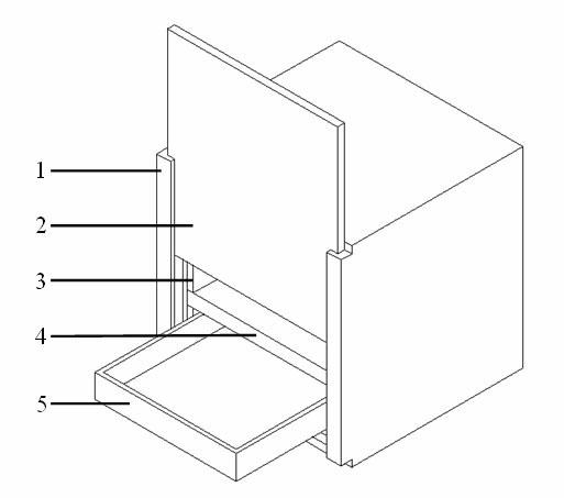
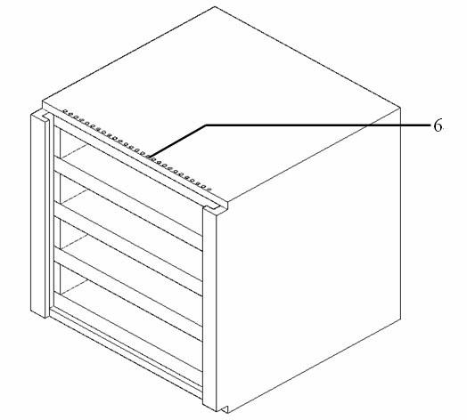
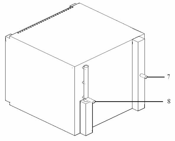
[0025] Such as figure 1 , figure 2 , image 3 and Figure 4 As shown, a low-melting-point alloy phase change heat storage device applied to a solar dryer, which includes a drying chamber box 1, a pull-out material box 5, a heat storage block 4, and an up and down sliding heat preservation door 2; The box body is made of thermal insulation blocks 3, and the upper part of the drying room box body has vent holes 6, and the outside of the drying room box body is covered with thermal insulation materials; 50 heat storage blocks 4 are arranged in the drying space of the drying room box body. The edge part of the heat block is supported by the insulation block and fixed to the drying chamber box; the pull-out material box is located between the upper and lower heat storage blocks and is in contact with the lower heat storage block, and the dry sample is contained in the pull-out type material box; Insert the left and right sides of the up and down sliding heat preservation door i...

Embodiment 2

[0040] Basically the same as Example 1, the difference is:

[0041] The appearance size of the heat storage block is 2000×2000×30mm, the distance between the upper and lower heat storage blocks is 100mm, and the amount of heat storage blocks in the dry space is 30. The heat storage capacity of the device at 100-300°C is 3.305×10 6 kJ, the heat exchange process in the device is sufficient and reversible, and the heat exchange efficiency is high. It can be used as heat storage device for solar dryer.

Embodiment 3

[0043] Basically the same as Example 1, the difference is:

[0044] The appearance size of the heat storage block is 1000×1000×50mm, the distance between the upper and lower heat storage blocks is 200mm, and the amount of heat storage blocks in the dry space is 15. The heat storage capacity of the device at 100-300°C is 6.887×10 5 kJ, the heat exchange process in the device is sufficient and reversible, and the heat exchange efficiency is high. It can be used as heat storage device for solar dryer.


PUM

PropertyMeasurementUnit
thicknessaaaaaaaaaa
phase transition temperatureaaaaaaaaaa
thicknessaaaaaaaaaa

Abstract

The invention relates to a low melting point alloy phase change heat storage device applied to a solar dryer, which is characterized by comprising a drying chamber box body, a drawing type material containing box, heat storage blocks and an upper and lower sliding type heat insulation door. Two to one hundred heat storage blocks are arranged in a drying space of the drying chamber box body, and the edge parts of the heat storage blocks are supported by the heat insulation blocks to be fixed with the drying chamber box body. The drawing type material containing box is located between an upper heat storage block and a lower heat storage block and is contacted with the lower heat storage bock, and drying samples are contained in the drawing type material containing box. Each heat storage block is composed of a heat storage material container, a heat storage material, a heat conducting pipe and heat conducting oil. The heat storage materials are encapsulated in the heat storage material containers, the heat conducting pipes are arranged in the heat storage material containers, the heat storage materials are encapsulated between the inner walls of the heat storage material containers and the outer walls of the heat conducting pipes, and the heat conducting oil serves as a heat conducting medium in the heat conducting pipes. The low melting point alloy phase change heat storage device applied to the solar dryer has the advantages of being convenient in feeding and discharging, reliable, safe and high in drying efficiency.

Description

technical field [0001] The invention relates to a low melting point alloy phase change heat storage device applied to a solar dryer. Background technique [0002] Solar drying is the oldest and most widely used form of human utilization of solar energy. Traditional solar drying is to put food and agricultural by-products directly under the sun for drying, which belongs to passive drying. This open-air natural drying method has many disadvantages: low efficiency, long cycle, large floor area, susceptible to showers, moldy rain and other climatic conditions, and also susceptible to pollution by wind, sand, dust, flies, insects, etc., it is difficult to guarantee The quality of dried food and agricultural by-products. [0003] In order to more effectively use solar radiation energy to dry materials, people have designed and built various types of solar dryers according to the drying characteristics of materials in combination with solar energy resources and climatic condition...

Claims


Application Information

Patent Timeline
Patent Type & Authority Applications(China)
IPC IPC(8): F26B9/10F28D20/02F26B25/06C09K5/06
CPCY02E70/30Y02E60/145Y02E60/14
Inventor 李元元程晓敏俞铁铭朱教群周卫兵
Owner WUHAN UNIV OF TECH
Learn More