
Ultra-wideband combination parallel voltage-dividing digital/analog variable attenuator

An ultra-wideband and attenuator technology, applied in the field of phased array radar, can solve the problems that the electrical performance index of the attenuator is difficult to meet the requirements, the VSWR difference between the input and output terminals is large, and the electrical performance consistency between circuits is poor. Excellent comprehensive electrical performance index, small insertion loss, and great improvement in electrical performance

Inactive Publication Date: 2012-08-01
CHANGSHU RES INSTITUE OF NANJING UNIV OF SCI & TECH
View PDF3 Cites 4 Cited by
  • Summary
  • Abstract
  • Description
  • Claims
  • Application Information

AI Technical Summary

Problems solved by technology

[0004] Due to the defects of the circuit topology and process implementation method used in the design, especially for the application requirements of wide frequency bandwidth and large attenuation, the electrical performance indicators of general attenuators are usually difficult to meet the requirements
The main disadvantages are: 1) The circuit topology is complex; 2) The design is difficult; 3) The process is difficult; 4) The attenuation accuracy is low; 5) The working frequency band is narrow; When the amplitude changes, the accompanying signal phase changes greatly; 7) The voltage standing wave ratio of the input and output terminals of each attenuation state is greatly different; 8) Affected by the process control parameters, the electrical performance consistency between the circuits is poor; 9) The circuit size is small Big
In particular, the large phase difference between each decay state is a common shortcoming of many similar products, which limits the wide application of this type of product in phased array radar systems and many advanced communication systems and weapon systems

Method used

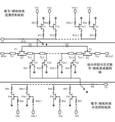

Image

  • Ultra-wideband combination parallel voltage-dividing digital/analog variable attenuator
  • Ultra-wideband combination parallel voltage-dividing digital/analog variable attenuator
  • Ultra-wideband combination parallel voltage-dividing digital/analog variable attenuator

Examples


Embodiment

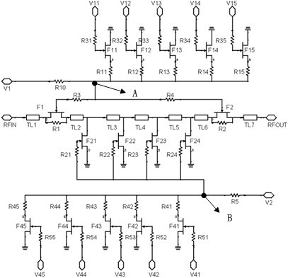
[0014] Example: figure 2 A five-bit control voltage ultra-wideband combined parallel divider digital / analog variable attenuator IC is shown.

[0015] Such as figure 2 As shown, the five-bit control voltage ultra-wideband combined parallel voltage-dividing digital / analog variable attenuator integrated circuit consists of a microwave signal input terminal RFIN; a microwave signal output terminal RFOUT; control signal input terminals V1, V11, V12, V13, V14, V15, V2, V41, V42, V43, V44, V45; voltage divider resistors R10, R11, R12, R13, R14, R15, R5, R41, R42, R43, R44, R45; voltage divider control field effect transistor F11 , F12, F13, F14, F15, F41, F42, F43, F44, F45; attenuation field effect transistors F1, F2, F21, F22, F23, F24; bias resistors R3, R4, R21, R22, R23, R24, R31, R32, R33, R34, R35, R51, R52, R53, R54, R55 and connection attenuation resistance R1, R2 constitute.

[0016] Such as figure 2As shown, in the ultra-wideband combined parallel voltage-dividing d...


PUM


Abstract

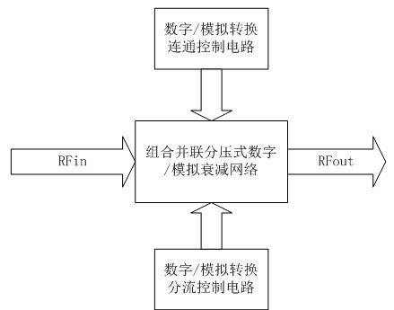
The invention discloses an ultra-wideband combination parallel voltage dividing digital / analog variable attenuator, which is formed by three parts of a connected control circuit, a shunt control circuit and an attenuation network circuit. Control voltage of connected attenuation and shunt attenuation in the attenuation network is provided by dividing of serial-parallel resistance voltage. The circuit is simple in topological structure, small in attenuation and phase-shift, low in insertion loss, high in attenuation accuracy, small in standing-wave ratio of output terminals and input terminals, wide in working band and small in circuit size and is convenient to be subjected to mass production by an MMIC (monolithic microwave integrated circuit) process. The ultra-wideband combination parallel voltage dividing digital / analog variable attenuator is designed closely according to related parameters provided by MMIC processing lines, and is a core component of transceiver modules of a modern phased array radar system and is very important.

Description

technical field [0001] The invention relates to the field of phased array radar, in particular to an ultra-wideband combined parallel voltage-dividing digital / analog variable attenuator. Background technique [0002] The GaAs-based ultra-wideband combined parallel voltage-dividing digital / analog variable attenuator is an electronic component mainly used in electronic system equipment such as digital microwave communication, mobile communication, radar, electronic countermeasures, guidance and instruments. In the control circuit of the ultra-wideband microwave and millimeter wave frequency band, the microwave and millimeter wave attenuator is one of the main control circuits, and the variable attenuator is applied to: 1) the broadband gain control block of the automatic loss control (ALC) component; 2) the broadband With pulse modulator; 3) broadband non-reflection single-pole single-throw (SPST) switch; 4) broadband vector modulator; 5) broadband automatic gain control (AGC)...

Claims


Application Information

Patent Timeline
IPC IPC(8): H03H7/24
Inventor 戴永胜李旭吴建星韦晨君施淑媛郭风英戚湧吴迎春陈建锋范小龙韩群飞尹洪浩左同生冯媛谢秋月李平孙宏途汉敏王立杰陈少波徐利周聪张红陈曦於秋杉杨健
Owner CHANGSHU RES INSTITUE OF NANJING UNIV OF SCI & TECH
Learn More