
Artificial hip joint friction pair surface film layer and preparation method thereof

A technology of hip joints and friction pairs, which is applied in the field of metal surface film and its preparation, can solve problems such as implant failure, reduce the internal stress of the film, solve the wear of the joint head and socket, and reduce wear

Inactive Publication Date: 2012-08-08
GUANGZHOU RES INST OF NON FERROUS METALS +1
View PDF7 Cites 21 Cited by
  • Summary
  • Abstract
  • Description
  • Claims
  • Application Information

AI Technical Summary

Problems solved by technology

[0008] The invention aims at the problem of friction and wear of the ball head and the acetabulum of the artificial hip joint friction pair and the implant failure caused by wear debris, and provides a metal-to-metal artificial hip joint friction pair ball head and acetabular surface film layer

Method used


Image

  • Artificial hip joint friction pair surface film layer and preparation method thereof
  • Artificial hip joint friction pair surface film layer and preparation method thereof
  • Artificial hip joint friction pair surface film layer and preparation method thereof

Examples


Embodiment 1

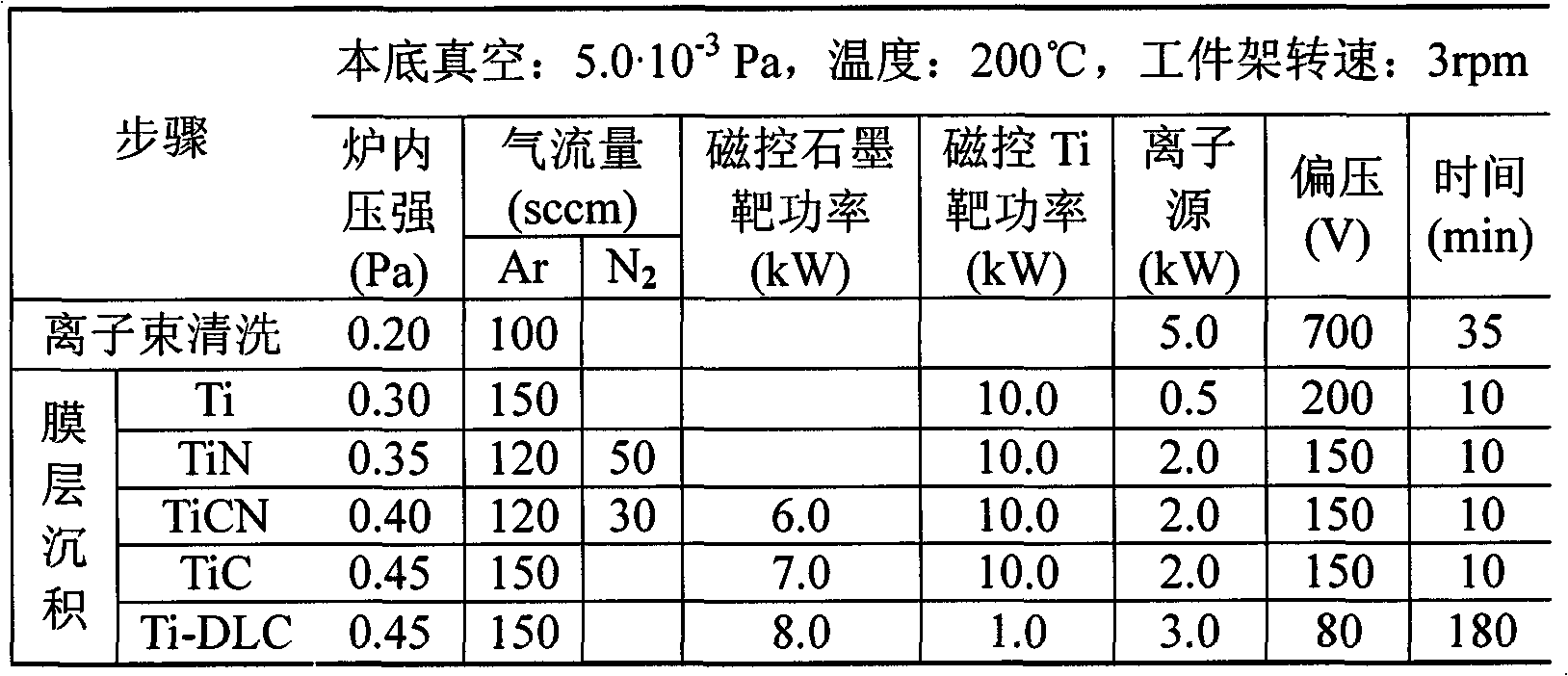
[0029] Table 1 Ti-DLC film process flow chart

[0030]

[0031] Ti targets are used, the gas is 99.99% argon and nitrogen, the ball head and acetabulum of the artificial hip joint are placed in a multi-functional ion coating machine, and Ti / TiN / TiCN / TiC / Ti-DLC layers are deposited in sequence, and the thicknesses are respectively 100nm, 200nm, 200nm, 200nm and 2000nm. The total thickness of the film layer is 2.7 μm. The surface color of the deposited artificial hip joint is uniform. The hardness value is Hv2300. 1.8×10 -19 m 3 / N·m.

Embodiment 2

[0033] Table 2 Cr-DLC film process flow chart

[0034]

[0035] Using a Cr target, the gas is 99.99% argon and nitrogen, and the artificial hip joint specimen is placed in a multifunctional ion coating machine, and Cr / CrN / CrCN / CrC / Cr-DLC layers are deposited in sequence, with thicknesses of 200nm, 300nm, and 300nm respectively. , 300mm and 3600nm. The total thickness of the film layer is 4.70 μm, the surface color of the deposited artificial hip joint is uniform, the hardness value is Hv2800, the bonding force of the film base is 72N, the dry friction coefficient of Cr-DLC to Cr-DLC is 0.09, and the measured average wear rate 4.4×10 -20 m 3 / N·m.

Embodiment 3

[0037] Table 3 Ta-DLC film process flow chart

[0038]

[0039] Using Cr and Ta targets, the gas is 99.99% argon and 99.9% nitrogen, and the artificial hip joint specimen is placed in a multifunctional ion coating machine to deposit Cr / CrN / CrCN / CrC / Ta-DLC multilayer films in sequence, with different thicknesses. 100nm, 200nm, 200nm, 200nm and 1500nm. The total thickness of the film layer is 2.30 μm. The surface color of the deposited artificial hip joint is uniform. The hardness value is Hv2500. 1.2×10 -19 m 3 / N·m.


PUM

PropertyMeasurementUnit
Thicknessaaaaaaaaaa
Total thicknessaaaaaaaaaa

Abstract

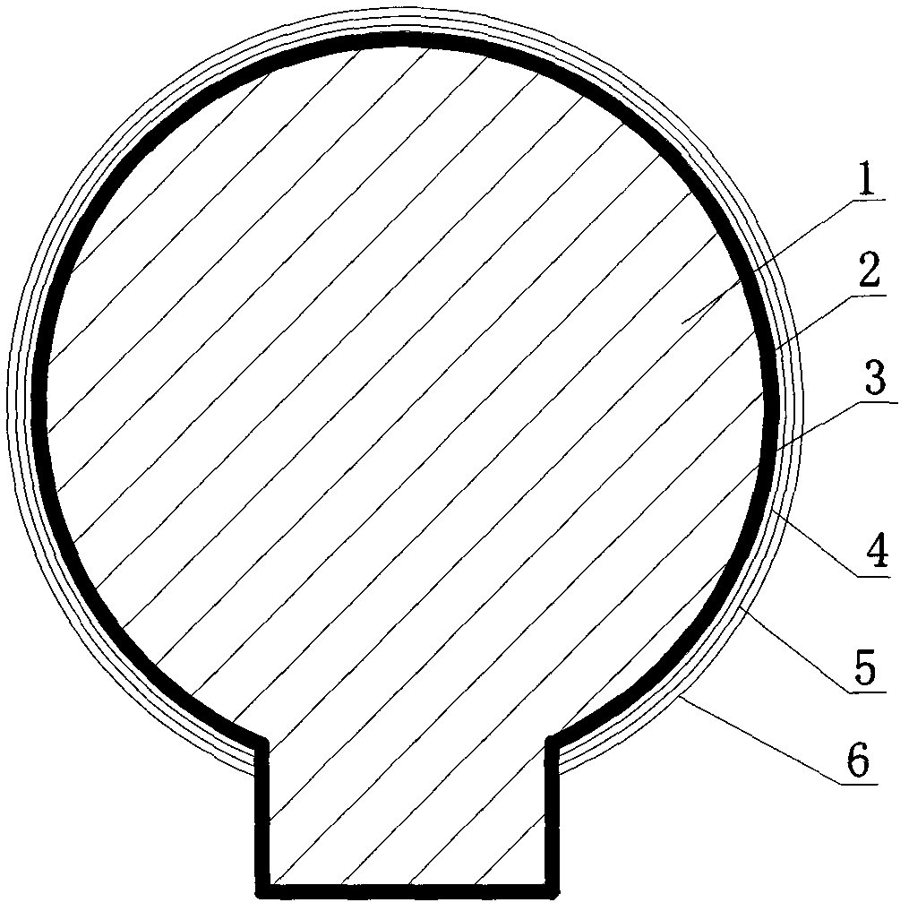
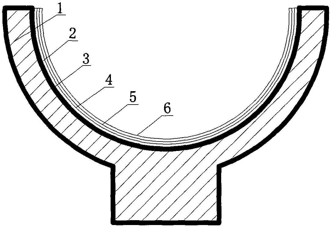
Provided are an artificial hip joint friction pair surface film layer and a preparation method thereof. The artificial hip joint friction pair surface film layer is characterized by being sequentially composed of a substrate (1), a metal layer (2), a metal nitride layer (3), a metal carbonitride layer (4), a metal carbide layer (5) and a metal-mixed diamond layer (6). The preparation method sequentially includes the steps of washing the substrate with ion beams and depositing the metal layer, the metal nitride layer, the metal carbonitride layer, the metal carbide layer and the metal-mixed diamond layer. The artificial hip joint friction pair surface film layer greatly reduces friction coefficient of a friction pair bulb and the acetabulum, reduces abrasion of a metal base body and release of metal ions, prolongs service life of the artificial hip joint, and resolves the failure problem of joint implanting of the artificial hip joint caused by joint head mortar abrasion and abrasive dust. Tests for simulating the human environment show that the artificial hip joint has excellent chemical inertness and biocompatibility, and is free of harmful tissue reaction and allergic reaction and high in safety.

Description

technical field [0001] The invention relates to a metal surface film layer and a preparation method thereof, in particular to a surface film layer of an artificial hip joint friction pair and a preparation method thereof. Background technique [0002] The artificial hip joint friction pair is composed of a prosthetic ball head and an acetabulum. At present, the main problem of the metal-on-ultrahigh-molecular-weight polyethylene (UHWPE) artificial hip joint is that the friction and wear of the friction pair interface leads to the failure of the joint implant, and the long-term life is not good. With the aging of the population, the increase of obese people and the increase of traffic accidents, artificial joint replacement is showing a trend of younger people. Twenty years ago, artificial joint replacement was mainly for patients over the age of 65, but now more patients under the age of 65 receive artificial joint replacement surgery. Therefore, the focus of research on a...

Claims


Application Information

Patent Timeline
IPC IPC(8): A61L27/30A61L27/04A61L27/06B32B15/04B32B9/04C23C14/35C23C14/16
Inventor 林松盛代明江朱向东樊渝江侯惠君胡芳韦春贝石倩周克崧张兴栋
Owner GUANGZHOU RES INST OF NON FERROUS METALS
Learn More