Photoelectric continuous liquid level measuring method and device

A liquid level measuring device and a technology for liquid level measurement, which are applied to measuring devices, liquid/fluid solids measurement, lubrication indicating devices, etc., can solve problems such as inability to perform accurate liquid level measurement, and achieve convenient maintenance, free assembly, and convenient transportation. Effect

Active Publication Date: 2012-08-22
POLYMER (SUZHOU) SENSING TECH CO LTD
View PDF6 Cites 29 Cited by
  • Summary
  • Abstract
  • Description
  • Claims
  • Application Information

AI Technical Summary

Problems solved by technology

In order to overcome the situation that the existing technology cannot meet

Method used


Image

  • Photoelectric continuous liquid level measuring method and device
  • Photoelectric continuous liquid level measuring method and device
  • Photoelectric continuous liquid level measuring method and device

Examples


Embodiment 1

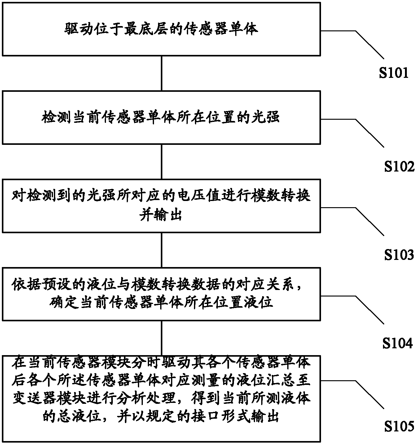
[0081] Based on the above core idea, the first embodiment specifically discloses a photoelectric continuous liquid level measurement method performed by a photoelectric continuous liquid level measurement device based on a sensor module composed of cascaded N sensor units. Wherein, N is greater than or equal to 1, the specific process of the method is as follows figure 1 As shown, it mainly includes the following steps:

[0082] Step S101, driving the sensor unit at the bottom;

[0083] Step S102, detecting the light intensity at the position of the current sensor unit;

[0084] During the execution of step S102, when driving from bottom to top, the current sensor unit is the sensor unit currently in the driving state.

[0085] Step S103, performing analog-to-digital conversion and outputting the voltage value corresponding to the detected light intensity;

[0086] In the process of executing step S103, when the current sensor unit is driven to detect the light intensity at...

Embodiment 2

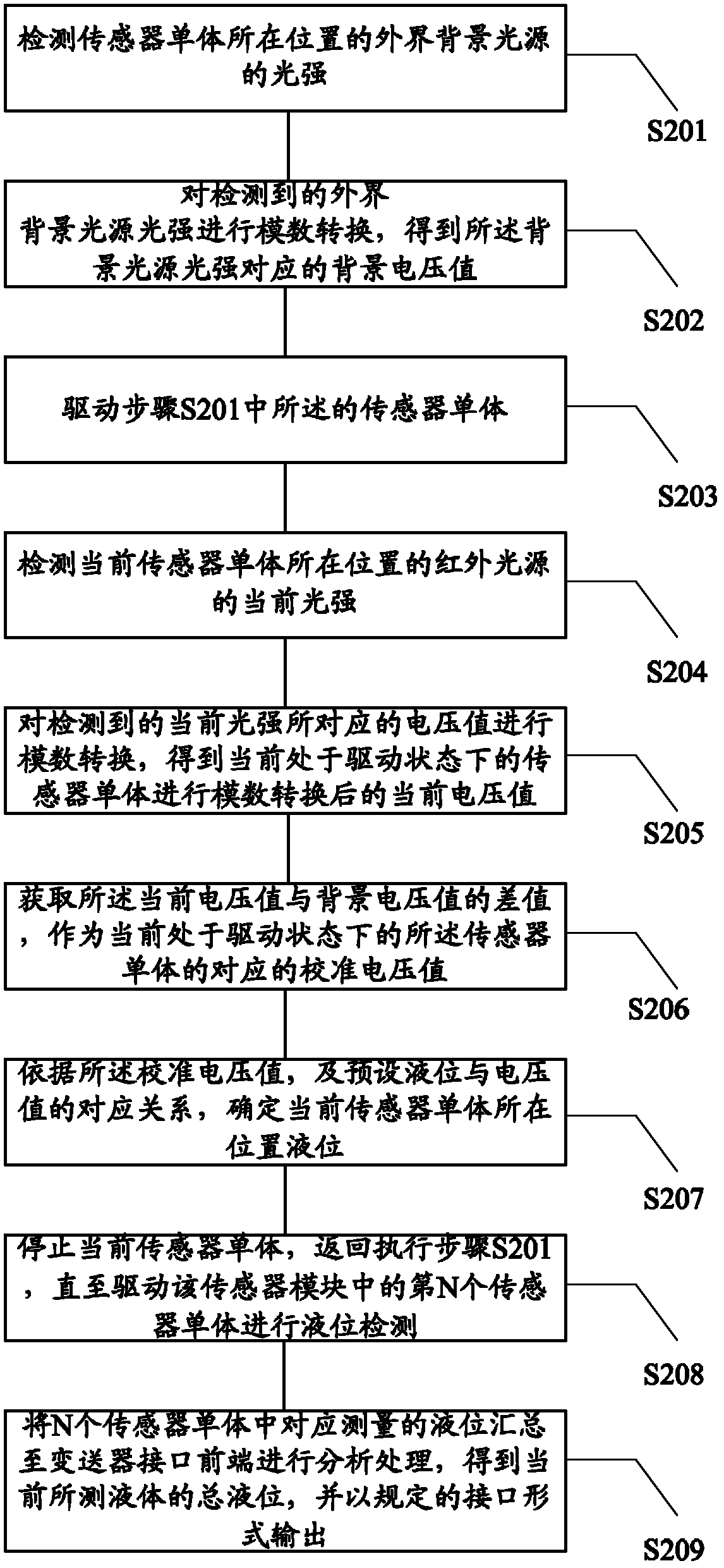
[0093] Based on the method of the first embodiment above, in the actual measurement process using the photoelectric continuous liquid level measuring device, the data obtained by analog-to-digital conversion contains two parts of the effect of light on the phototransistor: one part is the infrared LED light source, which is The other part of the useful signal is the background light source of the external environment. If there is fluctuation in this part of the light source, it will affect the measurement result, and we need to filter it out. Therefore, in order to avoid the influence of the light intensity of the background light source on the process of continuously measuring the liquid level. The second embodiment of the present invention, on the basis of the above-mentioned embodiments, is based on a photoelectric continuous liquid level measuring device based on a sensor module composed of N sensor monomers cascaded, wherein N is a positive integer greater than or equal to...

Embodiment 3

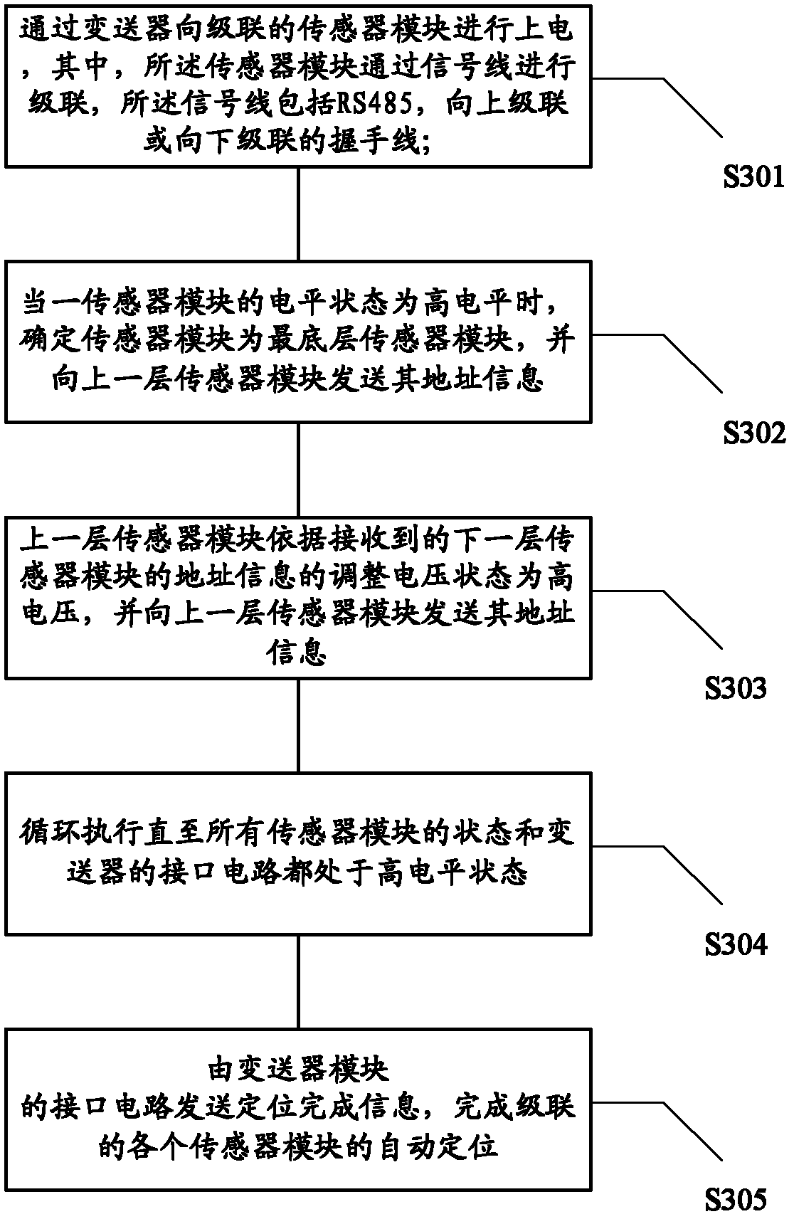
[0106] Based on the methods of the above embodiments, in actual use, the height of the carrier to be measured on-site is about 30 cm to 200 cm, and the height is not certain. The adopted sensor module cannot be assembled according to the measuring range when leaving the factory, and the sensor module assembled into a measuring range of 200 centimeters is also inconvenient to transport.

[0107] Therefore, when the measuring range of the required liquid level is relatively large, cascade connection of multiple sensor modules can be used for continuous liquid level measurement. When there are two or more cascaded sensor modules in the photoelectric continuous liquid level measuring device, this embodiment of the present invention discloses an automatic positioning method during the process of assembling the sensor modules, the process of which is as follows image 3 As shown, it mainly includes the following steps:

[0108] Step S301, supplying power to the cascaded sensor modu...


PUM

PropertyMeasurementUnit
Heightaaaaaaaaaa
Outer diameteraaaaaaaaaa
The inside diameter ofaaaaaaaaaa

Abstract

The invention provides a photoelectric continuous liquid level measuring method and a photoelectric continuous liquid level measuring device. The photoelectric continuous liquid level measuring method comprises the steps of driving a current sensor monomer from bottom to up to detect the light intensity fed back from the position of the sensor monomer under the control of a sensor module; carrying out analog-digital conversion on a voltage corresponding to the detected light intensity; determining the liquid position of the position of the current sensor monomer according to the corresponding relationship of a preset liquid level and the analog-digital data; and after the measurement of the liquid level of the position of other sensor monomers under the time-sharing control of corresponding sensor modules is accomplished, summarizing the liquid level of each sensor monomer to the front end of a transmitter interface through data transmission between modules; and obtaining a total liquid level of the current liquid after analysis and process and outputting the liquid level in specified interface mode. The device adopts the modular construction which is assembled and positioned freely according to the requirement of the measuring range, the applicability of different measuring ranges is improved, and the transportation is convenient; and furthermore, the real time self-correcting function is provided, and the capability of pollution resistance and shifting is improved.

Description

technical field [0001] The invention belongs to the technical field of container calibration, in particular to a photoelectric continuous liquid level measurement method and device. Background technique [0002] The material level includes liquid level and material level. There are two ways to measure the liquid level, including the use of liquid level indicators and continuous liquid level measurement. The liquid level signal device measures the liquid level at several fixed positions, and is used for the upper and lower limit alarms of the liquid level. Continuous liquid level measurement is the continuous measurement of liquid level, which is widely used in many fields such as petroleum, chemical industry, food processing and so on. [0003] At present, the methods applied to continuous liquid level measurement include: manual measuring method, floating ball method, servo valve, static pressure method, magnetostrictive method, ultrasonic method, optical fiber sensor met...

Claims


Application Information

Patent Timeline
IPC IPC(8): G01F23/292
CPCG01F23/2927G01J5/20G01F23/80G01F23/0007G01F23/00G01F23/292
Inventor 付俊于连波常伟
Owner POLYMER (SUZHOU) SENSING TECH CO LTD
Why Eureka
Try Eureka