Compressed air energy storage system

A technology of energy storage system and compressed air, which is applied to the components of pumping devices for elastic fluids, non-variable-capacity pumps, pump devices, etc. Production and other problems, to achieve the effect of simple system composition and high energy conversion efficiency

Inactive Publication Date: 2012-09-12
XI AN JIAOTONG UNIV
View PDF10 Cites 52 Cited by
  • Summary
  • Abstract
  • Description
  • Claims
  • Application Information

AI Technical Summary

Problems solved by technology

[0008] 2. The structure of the compressor in the system uses a water-cooled intercooler and aftercooler, and the heat released by the gas during the compression process is not recovered
[0009] 3. No gas turbine is installed in the system
[0013] First generation systems require an external heat source to supplement heat to the system, but do not recover the heat generated during compression
In addition, since the system does not use a gas turbine, the effective energy contained in the fuel has not been fully utilized; the total conversion efficiency of the system will not be very high; since the units are directly connected, the main engine (compressor and gas turbine expander ) selection is limited, which is not conducive to mass production of equipment
[0014] The gas turbine unit is introduced into the second-generation system, and the exhaust heat of the gas turbine or the high-temperature gas extracted in the middle are used as the heating source of the compressed air. Although the specific efficiency and power generation efficiency of the system will be greatly improved, a large amount of gas is required. This compressed air energy storage The power station is not suitable for applications in arid areas that lack natural gas, or where natural gas is expensive and water is scarce

Method used


Image

  • Compressed air energy storage system
  • Compressed air energy storage system
  • Compressed air energy storage system

Examples


Embodiment Construction

[0025] The present invention will be described in detail below in conjunction with the accompanying drawings.

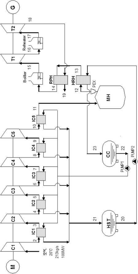
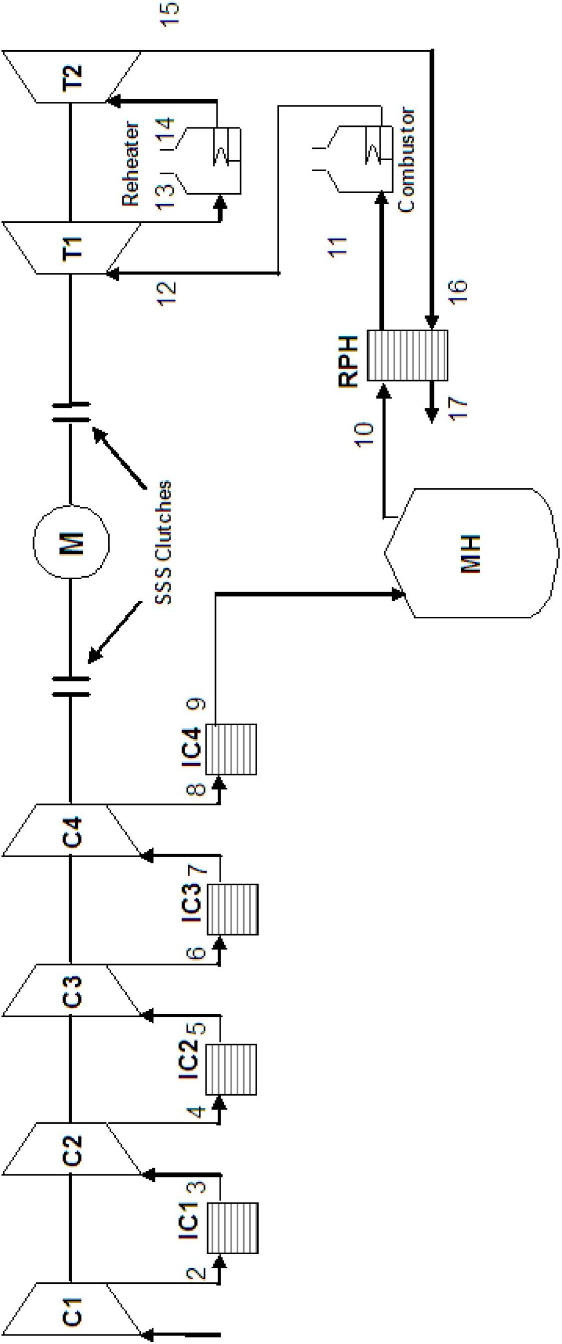
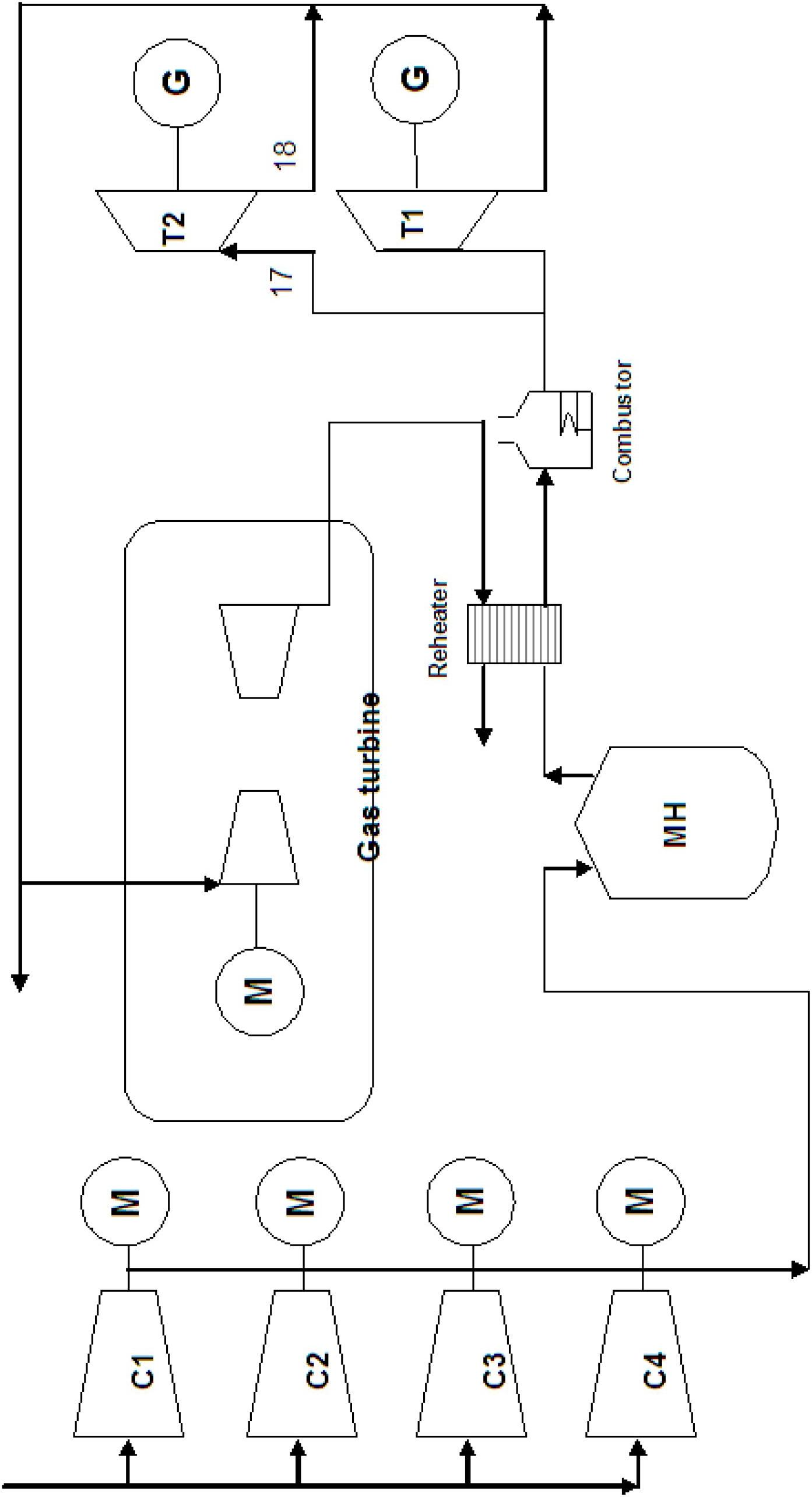
[0026] Such as image 3 As shown, the system of the present invention includes compressors C1, C2, C3, C4, C5; turbo expanders T1, T2; intercoolers IC1, IC2, IC3, IC4; motor M; generator G; HST; cold water storage tank CC; pre-expansion device PEX; hot water storage tank HST; regenerator RPH; air heater boiler.

[0027] The system uses the inexhaustible electric energy during the low power consumption period of the user or the peak period of wind farm power generation to drive the compressor units C1, C2, C3, C4, and C5 to work, compress the air under normal pressure to high pressure, and pass through the intercooler IC1, IC2, IC3, and IC4 cool the high-pressure air, and the cooled high-pressure air is stored in the high-pressure gas storage mine MH. The intercoolers IC1, IC2, IC3 and IC4 are stored in the hot water storage tank HST to cool the high-pressure gas to...


PUM


Abstract

The invention discloses a compressed air energy storage system, which comprises a compressor unit, a pre-expansion device, a turbine expansion machine, an intermediate cooler, an electric motor, a power generator, a hot water storage tank and a cold water storage tank, wherein the system utilizes electric energy which is not used up in the user electricity consumption valley period or wind power station power generation peak period for driving the compressor unit to work, the air at the normal pressure is compressed to high pressure, in addition, the part of air with rich pressure energy is stored into a high-pressure-resistance hole, in addition, the stored high-pressure air is released in the user electric consumption peak period or the wind power field generation valley period, an expansion unit is pushed to apply work, and the electric energy is output. The air pre-expansion device is additionally arranged at an outlet of an air storage chamber, so the air inlet pressure of the air turbine expansion machine is stable, the work stability of a power generation system is enhanced, low-temperature air at an outlet of the pre-expansion device is utilized for cooling hot water from the hot water storage tank, the temperature of the low-temperature air is raised through absorption of heat from the hot water, and the cooled water enters the cold water storage tank. The compressed air energy storage system is provided with the hot water storage tank and the cold water storage tank, the water is cyclically utilized in a closed loop, the water is not consumed, in addition, the heat discharged by the compressor is fully utilized and conveyed back to the high-pressure air at the outlet of the pre-expansion device. The high-pressure air at the outlet of the pre-expansion device is recovered through a heat recovering device (HRH).

Description

Technical field: [0001] The patent of the present invention relates to the field of air energy storage, in particular to an energy storage system for compressed air. Background technique: [0002] Judging from the current level of technological development, compressed air energy storage technology (CAES) and pumped storage technology are the only two technologies that can realize large-scale storage of electric energy. Due to the general drought and water shortage in the vast western regions of our country, the pumped storage technology cannot be used temporarily. Therefore, the compressed air energy storage technology has become the only technology that can be used for large-scale storage of wind power in my country, especially in the western regions. [0003] Compressed air energy storage technology has been applied and developed abroad for more than 30 years, and it is still operating safely today. At present, the power stations in operation include the compressed air en...

Claims


Application Information

Patent Timeline
Patent Type & Authority Applications(China)
IPC IPC(8): F01D15/10F01D25/10F04D25/08F04D29/58
Inventor 王焕然程鹏席光孙中国王丽琴毛义军
Owner XI AN JIAOTONG UNIV
Why Eureka
Try Eureka