Piezoelectrically actuated micro-mixer, manufacturing method and control method of piezoelectrically actuated micro-mixer

A micro-mixer, piezoelectric drive technology, applied in chemical instruments and methods, pump control, mixers, etc., can solve the problems of difficult integration and miniaturization, difficult processing, poor mixing controllability, etc., and achieve mixing time. The effect of short mixing distance, simple structure and manufacturing process, and high feature size compatibility

Inactive Publication Date: 2012-09-19
JILIN UNIV
View PDF3 Cites 19 Cited by
  • Summary
  • Abstract
  • Description
  • Claims
  • Application Information

AI Technical Summary

Problems solved by technology

Disadvantages: difficult processing, low mixing efficiency, and poor mixing controllability; active micro-mixers require external energy to induce mixing, including: micro-stirring, pressure disturbance, acoustic wave disturbance, electrohydrodynamic and magnetohydrodynamic drive, etc.
But there are still the following disadvantages: the overall structure is complex, in addition to the surface acoustic wave generator, it still needs to be driven by a syringe pump; the volume is large, it is not easy to integrate and miniaturize; the production cost is high; there is working noise, etc.
However, there are the following disadvantages: sensitive to output back pressure; micropump has no cut-off; in the early stage of mixing, debugging operations such as filling the pump are required; mixing capacity and mixing mode are limited; mixing controllability is not high, etc.
Therefore, a large number of problems remain to be solved in fluid mixing at the microscale.

Method used


Image

  • Piezoelectrically actuated micro-mixer, manufacturing method and control method of piezoelectrically actuated micro-mixer
  • Piezoelectrically actuated micro-mixer, manufacturing method and control method of piezoelectrically actuated micro-mixer
  • Piezoelectrically actuated micro-mixer, manufacturing method and control method of piezoelectrically actuated micro-mixer

Examples


Embodiment 1

[0042] Example 1 Micro-mixer driven by a single-cavity single-oscillator piezoelectric pump

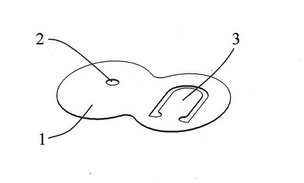
[0043] refer to figure 1, the one-way valve 3 with a cantilever beam structure and the middle access hole 2 are combined on the same substrate 1 to form an inverted "8"-shaped one-way valve plate. Check valve function for directional outflow. The variable stiffness design of the cantilever beam type one-way valve plate is realized by changing the thickness of the whole valve plate or the length of the cantilever of the valve, so as to improve the high-frequency response characteristics and outflow efficiency of the one-way valve. Among them, the inlet valve stiffness is lower than the outlet valve stiffness.

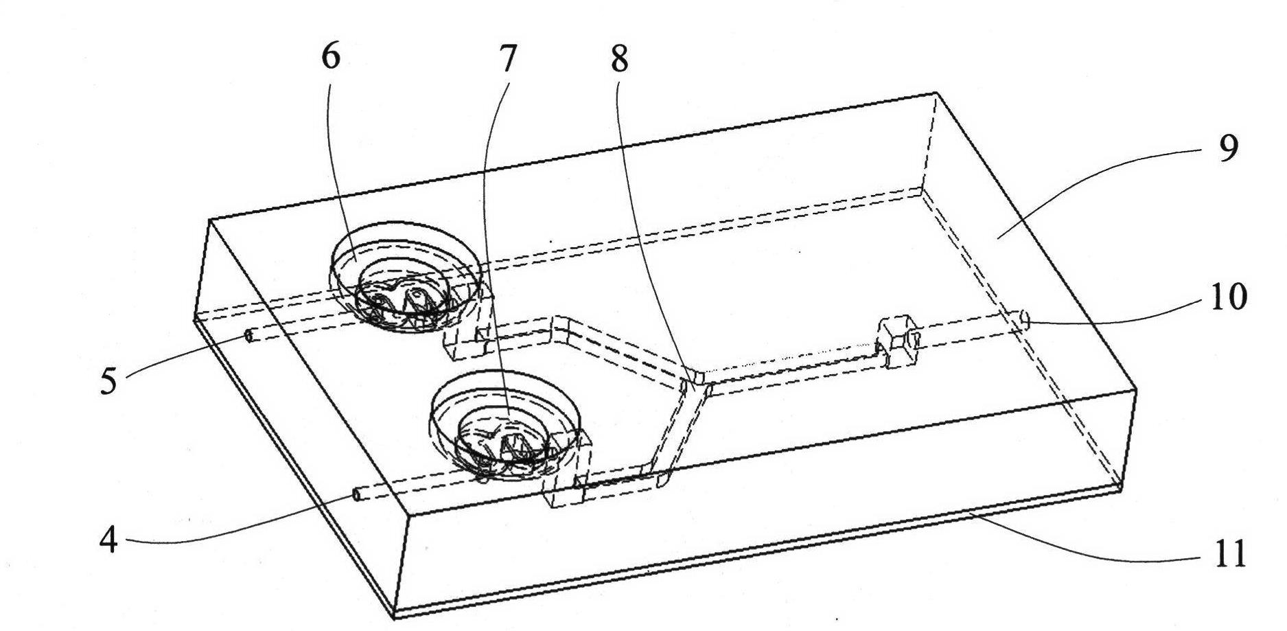
[0044] refer to figure 2 The PDMS substrate 9 integrates the piezoelectric pumps 6 and 7 and the micro-mixing channel 8, which includes two inlets 4, 5 and a mixing outlet 10. The substrate 9 is packaged with the glass bottom plate 11 to form the mixing channel 8.

[0045] ...

Embodiment 2

[0047] Example 2 A micro-mixer driven by a dual-cavity dual-oscillator serial piezoelectric pump

[0048] refer to Figure 5 , PDMS substrate 42 integrates two sets of piezoelectric pumps 39 and 40 and micro-mixing channel 41, which includes two inlets 37, 38 and mixing outlet 43, substrate 42 is packaged with glass bottom plate 44 to form mixing channel 41. Among them, each group of piezoelectric pumps adopts a double-cavity double-oscillator series structure.

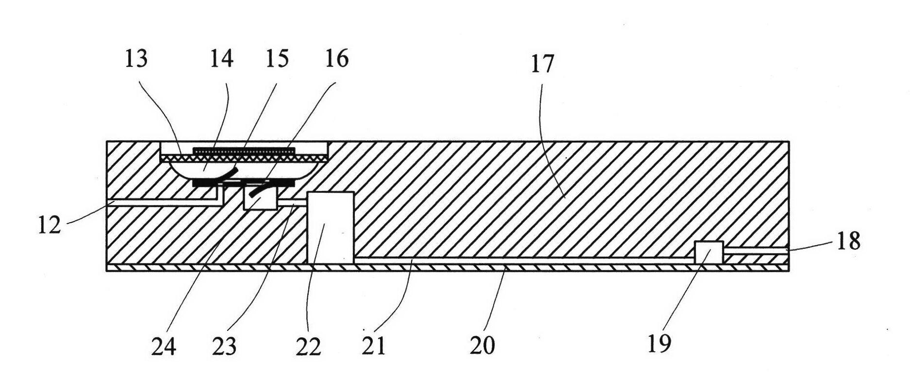
[0049] refer to Figure 6 , the working principle of each group of piezoelectric pumps and micro-mixers in Example 2 is: the piezoelectric vibrator 58 and the PDMS substrate 50 form an inlet cavity 61, the piezoelectric vibrator 46 and the PDMS substrate 50 form a series cavity 47, and the two cavities pass through The intermediate pipes 59 are connected in series. The one-way valve plate 60 is separately assembled on the PDMS substrate to form the inlet cantilever beam type one-way valve, and the middle valve plat...


PUM


Abstract

The invention discloses a piezoelectrically actuated micro-mixer, a manufacturing method and a control method of the piezoelectrically actuated micro-mixer, belonging to the technical field of a micro-mixer. With the adoption of the micro-mixer, a micro-fluid drive unit (namely a piezoelectric pump) and a micro-mixing unit (namely a mixing runner) are integrated into a whole via an overall PDMS (polydimethylsiloxan) substrate; a single chip piezoelectric vibrator and a one-way valve block are encapsulated together with the PDMS substrate to form the piezoelectric pump; a glass base plate is encapsulated together with the PDMS substrate to form the mixing runner; and the piezoelectric vibrator is stimulated by adopting different voltages, frequencies, different waveforms and phase staggered drive electric signals so as to achieve high-frequency pulsating displacement mixing of the micro-fluid in a micro-mixing runner. With the adoption of the piezoelectrically actuated micro-mixer, the defects of low mixing efficiency, long time and the like caused by that the micro-fluid is mixed by laminar diffusion under a micro-scale are effectively overcome, so that efficient turbulent mixing is realized. The piezoelectrically actuated micro-mixer disclosed by the invention has the advantages of being simple in manufacturing method, low in cost, high in mixing efficiency, short in time, small in volume and easy in integration, and capability of widely applying to the fields such as analytical chemistry, micro-chemical system, environment monitoring, life science and the like.

Description

technical field [0001] The invention belongs to the technical field of microfluid mixing, and in particular relates to a piezoelectric-driven micromixer, a manufacturing method and a control method thereof. Background technique [0002] As an important part of the microfluidic system, the micro-mixer is used to realize the full mixing of different reactants under micro-scale conditions. Application prospects. [0003] It is difficult to achieve rapid and effective mixing of microfluidics at the microscale, because the characteristic size of the microfluidic system belongs to the micron level, the Reynolds number is small (Re=0.1~100), the fluid maintains a laminar flow state, and the mixing completely depends on molecular diffusion It takes a long distance and time to mix evenly. Especially when dealing with reagents containing large molecules, achieving complete mixing becomes more difficult. [0004] Many researchers disrupt the flow field by changing the structure of t...

Claims


Application Information

Patent Timeline
Patent Type & Authority Applications(China)
IPC IPC(8): B01F13/00B01F15/02F04B49/06
Inventor 刘国君杨志刚刘建芳王浩李思明
Owner JILIN UNIV
Why Eureka
Try Eureka