Denitration method for waste gas generated by burning system and denitration device thereof

A combustion system and denitration technology, which is applied in the field of pollution control of NOx-containing waste gas, can solve the problems of difficult adjustment of reaction conditions, difficult control of reaction quality, and high cost of use, and achieves the advantages of shortening reaction time, lowering temperature and saving energy consumption. Effect

Inactive Publication Date: 2012-09-26
CESTOIL ENVIRO CO LTD
View PDF5 Cites 23 Cited by
  • Summary
  • Abstract
  • Description
  • Claims
  • Application Information

AI Technical Summary

Problems solved by technology

[0033] A further development is, for example, US Pat No 5,693,300 and US Pat No 4,886,650, through the use of metal catalysts to make ammonia and cyanic acid all or part of free radical active particles to react with NO x Reaction, the required reduction reaction temperature can be greatly reduced like this, but, this method needs to use precious metal catalyst, and use cost is higher, uses solid catalyst bed simultaneously and its reaction condition is more difficult to adjust, and its reaction quality is also difficult to control

Method used


Image

  • Denitration method for waste gas generated by burning system and denitration device thereof
  • Denitration method for waste gas generated by burning system and denitration device thereof
  • Denitration method for waste gas generated by burning system and denitration device thereof

Examples


Embodiment 1

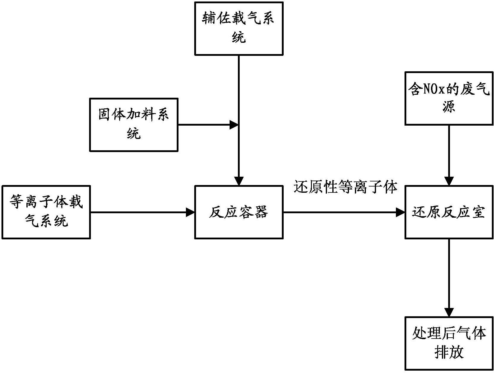
[0069] Such as figure 1 As shown, the solid reducing agent is added to the auxiliary carrier gas system by using the solid feeding system, and the auxiliary carrier gas system brings the solid reducing agent into the electrode area in the plasma reaction vessel or the reaction area behind the electrode area. In this area, the solid The reducing agent and the plasma from the plasma carrier gas system collide and exchange energy, so that they can be gasified and converted into plasma or excited activated molecules in whole or in part. This reducing plasma is introduced into the NO-containing plasma. x The exhaust gas channel, and enter the reduction reaction chamber together with the exhaust gas, under the action of the catalyst (SCR method) or a certain temperature (SNCR method), the NO x reduced to N 2 and CO 2 And water and other harmless gases, the treated gas is discharged through the subsequent discharge device.

Embodiment 2

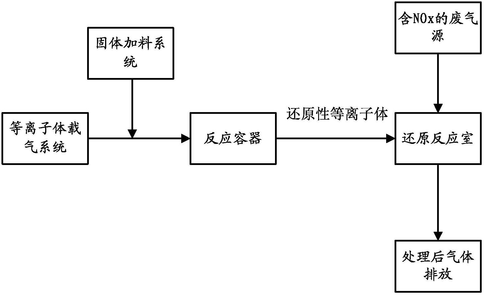
[0071] Such as figure 2 As shown, the solid reducing agent is directly added to the plasma carrier gas system by using the solid feeding system, and the plasma carrier gas brings the solid reducing agent into the electrode area in the plasma reaction vessel or the reaction area behind the electrode. Subsequent steps are the same as in Example 1.

Embodiment 3

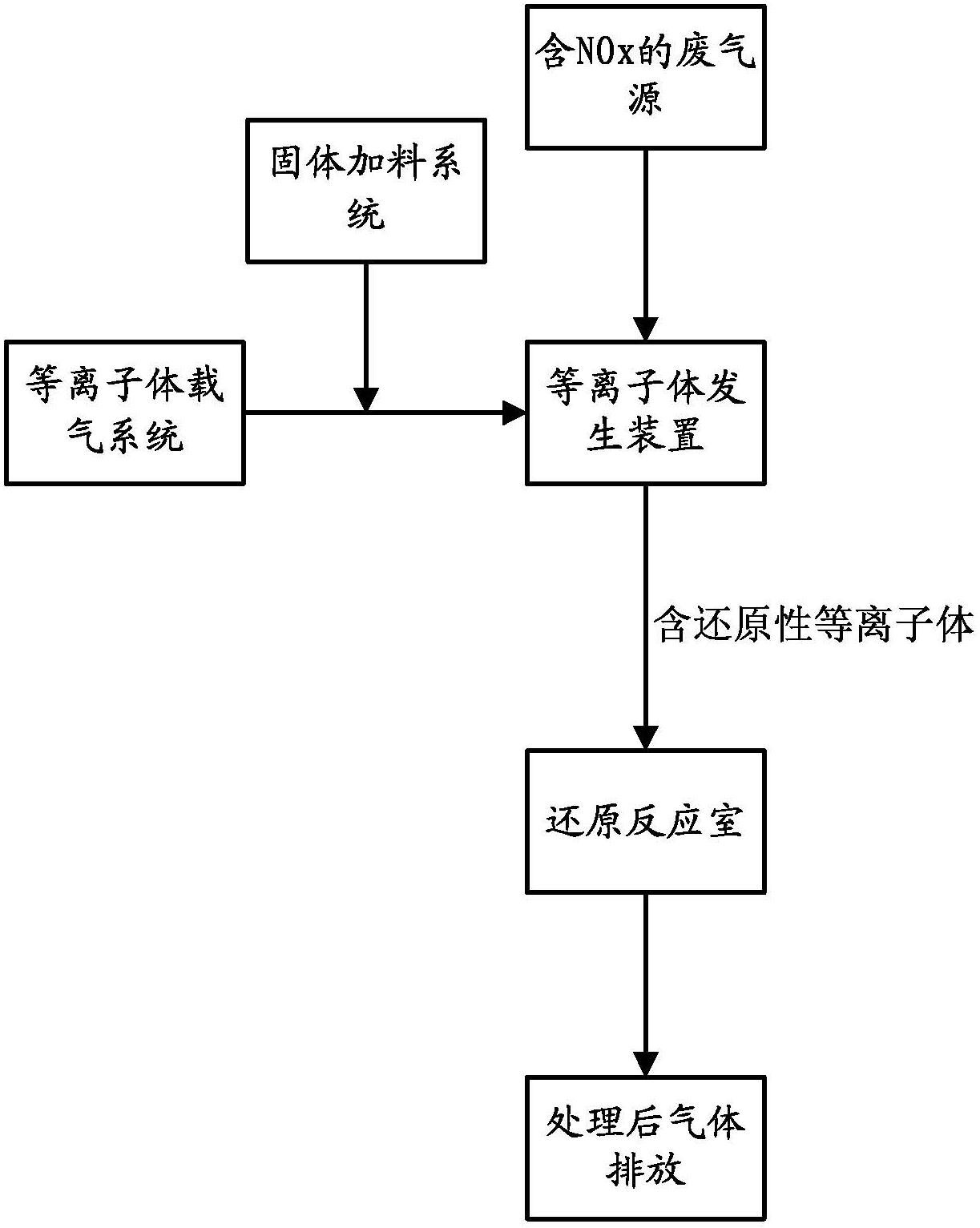
[0073] Such as image 3 As shown, the open plasma reaction device is adopted, and the plasma reaction device is placed in the exhaust gas passage, and the generated reducing plasma is quickly in contact with the exhaust gas. This process arrangement is especially suitable for plasma nozzles, plasma showers, and plasma torches. Applications of plasma devices. In such an arrangement, once the plasma is generated, it can quickly enter the reduction reaction, preventing the plasma from being quenched and annihilated. Subsequent steps are the same as in Example 1.


PUM


Abstract

The invention provides a denitration method for waste gas generated by a burning system and denitration equipment for the waste gas generated by the burning system. The denitration method comprises the following steps of: bringing reducing agent into an electrode region in a plasma reaction container or a reaction region behind the electrode region, where the reducing agent and plasma collide with each other and change the energy, and all or some of the reducing agent is transformed into plasma or is activated into the activated molecules, wherein the mixed gas is led into a NOx-containing waste gas channel, and enters into a reduction reaction room with the waste gas; reducing the NOx into harmless gas such as N2, CO2, and water in case of catalyst or high temperature; and discharging the treated gas through a follow-up discharger. According to the method, the use level of solid reducing agent can be greatly saved, the risk of the leakage of reducing agent components can be reduced, the reaction time can be shortened, and the reaction efficiency of a reactor can be improved.

Description

technical field [0001] The application of the present invention relates to a x The gas purification process can be used in the flue gas of power plants, the exhaust gas of internal combustion engines and other industrial processes that contain NO x Waste gas pollution control. Background technique [0002] It is well known that combustion processes produce large amounts of NO-containing x gas, NO x The concentration can reach hundreds or even thousands of ppmg. NO x It is the general term for all nitrogen oxides, about 90% of which are NO. NO x Released into the atmosphere will lead to the formation of acid rain and air pollution, and if NO enters the stratosphere of the atmosphere, it will also cause the destruction of the ozone layer. NO in flue gas / exhaust gas x It mainly comes from the oxidation of nitrogen-containing compounds in the fuel, and partly comes from the oxidation of molecular nitrogen in the air. In addition to the concentration of nitrogen-containi...

Claims


Application Information

Patent Timeline
Patent Type & Authority Applications(China)
IPC IPC(8): B01D53/76B01D53/86B01D53/56
Inventor 熊靓
Owner CESTOIL ENVIRO CO LTD
Why Eureka
Try Eureka