
Nano-particle identification system device and identification method thereof

A nanoparticle and system device technology, applied in measurement devices, particle size analysis, particle suspension analysis, etc., can solve the problems of fast measurement speed, inability to detect particle concentration, and inability to meet particle identification and quantification, so as to improve specificity and sensitivity. , Improve the effect of the scope of application

Active Publication Date: 2012-09-26
NANJING UNIVERSITY OF TRADITIONAL CHINESE MEDICINE
View PDF4 Cites 5 Cited by
  • Summary
  • Abstract
  • Description
  • Claims
  • Application Information

AI Technical Summary

Problems solved by technology

The measurement speed of this method is fast, and the smaller the particle, the larger the diffraction angle. Therefore, the astigmatism signal of the same size particle is different at different angles. At present, the single light source laser particle size detector can only meet the particle size distribution detection of particles in the solution. The identification and quantification of
[0007] At present, the detection technology of particle size distribution in solution is relatively mature, but for particles with close or similar particle size distribution in solution, the above particle size detection technologies are difficult to meet this requirement, and only the multi-point astigmatism signal is used for particle size analysis. , there is no method for quantitative calculation of particles at present, and the particle concentration cannot be detected

Method used


Image

  • Nano-particle identification system device and identification method thereof
  • Nano-particle identification system device and identification method thereof
  • Nano-particle identification system device and identification method thereof

Examples


Embodiment 1

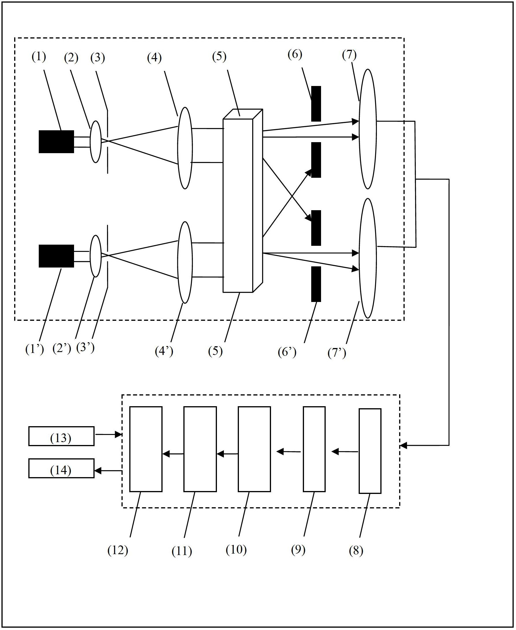
[0029]The nanoparticle identification system device includes a light scattering system, a data processing system and a detection pool 5. The light scattering system includes two groups of laser sources arranged in parallel in sequence. 1 is an EXF-7600B adjustable wavelength laser source, and a short-focus lens 2 The LL-771 low-loss lens, the grating 3 is the CD-00S6 fiber coupler type fiber grating of Xinsuo Electronics, the telephoto lens 4 is the NV-202m lens, the grating filter 6 is the RC7650 filter with a resolution of 0.2nm, The multi-point scattered light receiver 7 is a Picometrix LLC high-speed scattered light receiver module, which is arranged logarithmically at multi-point intervals. The detection pool 5 is arranged between the telephoto lens 4 and the grating filter 6, and the emission wavelength of the laser source is Between 375nm and 785nm, there are differences in the emission wavelength λ of different laser sources, and the difference Δλ between the emission w...

Embodiment 2

[0042] Quantitative calculation of endotoxin in embodiment 2 endotoxin, Tween-80 mixed solution

[0043] For bacterial endotoxin and Tween-80 aqueous solution with similar particle size, use the device and method of Example 1, and place the mixed solution of the above components in the detection cell.

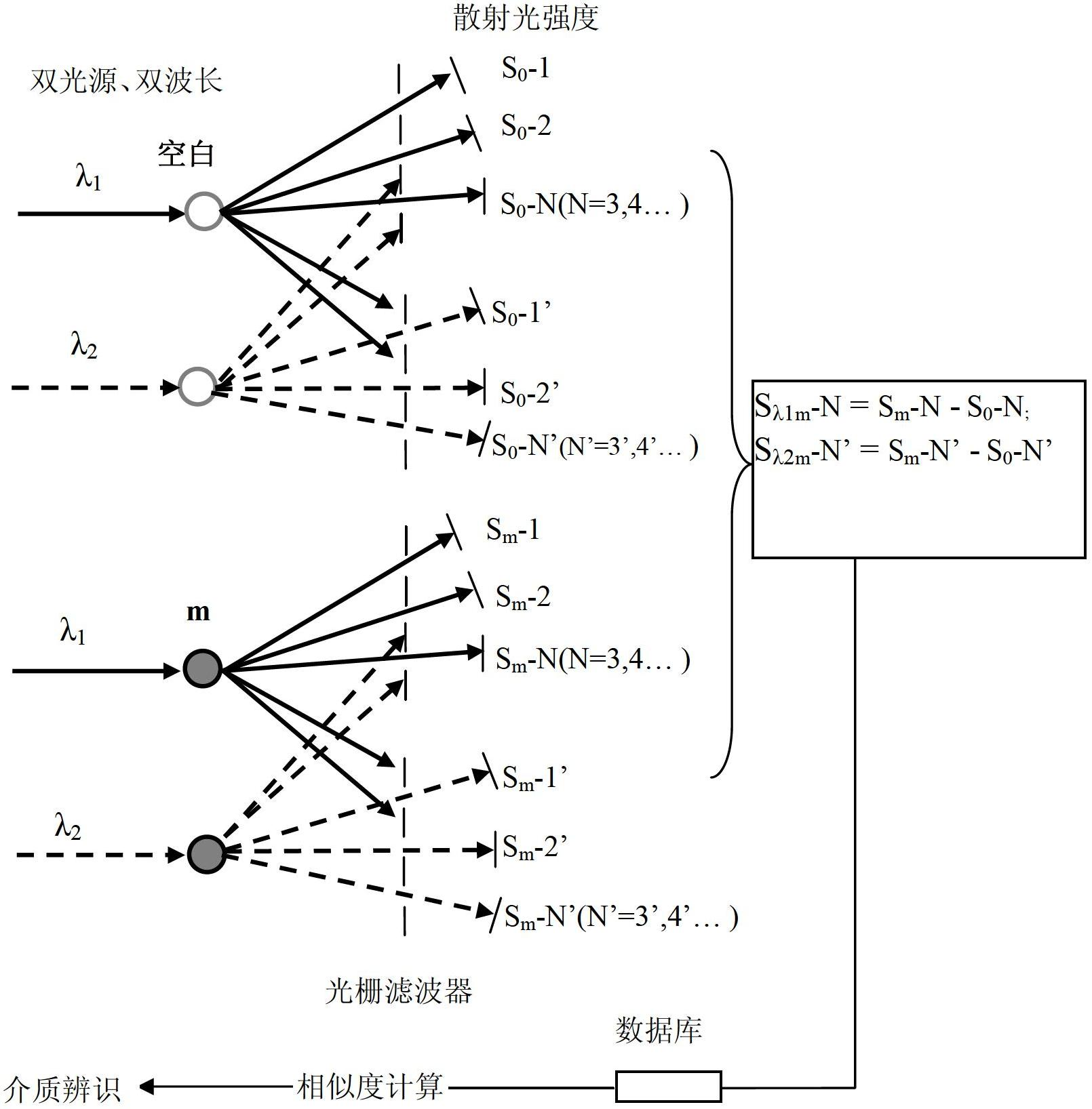
[0044] In the optical path system, the emission wavelength of the first laser source is set to 635nm, and different nanoparticles in the solution are irradiated through the optical path system, and the multi-point receiver for simultaneous detection at three angles receives and analyzes the scattered light of a specific wavelength passing through the grating filter;

[0045] Set the emission wavelength of the second laser source to 532nm, irradiate different nanoparticles in the solution through the optical path system, and the multi-point receiver for simultaneous detection at 3 angles receives and analyzes the scattered light of a specific wavelength passing through the gratin...

Embodiment 3

[0052] The used concrete equipment model of this embodiment is identical with embodiment 1:

[0053] The nanoparticle identification system device includes a light scattering system and a data processing system, and also includes a detection pool 5. The light scattering system includes at least two groups of laser sources 1 that are arranged in parallel in order, a short-focus lens 2, a grating 3, and a telephoto lens. Lens 4, grating filter 6 and multi-point scattered light receiver 7, the detection pool 5 is arranged between the telephoto lens 4 and the grating filter 6, the emission wavelength of the laser source is between 375nm~785nm, different laser There is a difference in the emission wavelength λ of the source, and the difference Δλ between the emission wavelengths is not less than 10nm; the data processing system includes a photoelectric conversion module 8, a data processing module and a display 14, and the data processing module includes a signal preprocessor 9, Da...


PUM

PropertyMeasurementUnit
Wavelengthaaaaaaaaaa

Abstract

The invention discloses a nano-particle identification system device and an identification method thereof. The nano-particle identification system device comprises a light scattering system and a data processing system, and further comprises a detector tank, wherein the light scattering system comprises at least two groups of laser sources which are arranged in sequence and parallel, a short-focus lens, an optical grating, a long-focus lens, an optical grating filter and a multi-point scattered light receiver; the detector tank is arranged between the long-focus lens and the optical grating filter; the data processing system comprises a photoelectric conversion module, a data processing module and a display; and curve similarity and particle concentration quantitative data are acquired by the data processing module through calculation, and then a result is displayed on the display. The method adopts a laser particle size detector to carry out laser radiation on target particles and interference particles in a solution, so as to achieve the identification on characteristics of nano-particles in the solution by calculating the curve similarity, and to further carry out targeted identification detection on particles with similar particle diameters in an aqueous solution.

Description

technical field [0001] The invention belongs to the technical field of particle size monitoring, and in particular relates to a device and an identification method capable of identifying the characteristics of nanoparticles in a solution. Background technique [0002] With the vigorous development of nanotechnology, nanoparticle identification and measurement technology in nanotechnology has gradually become a research hotspot, and its importance has been highlighted in scientific research and social applications. The properties of nanomaterials in the fields of electronics, optics, sintering of high-density materials, catalysis, and sensing are closely related to their particle size, so the accurate measurement and characterization of nanoparticle size is of great significance. Commonly used methods for detecting the particle size of nanoparticles are: X-ray diffraction (XRD), transmission electron microscopy (TEM), atomic force microscopy (AFM) and photon correlation metho...

Claims


Application Information

Patent Timeline
IPC IPC(8): G01N15/02G01N15/06
CPCG01N21/51G01N2021/4711G01N15/02G01N2021/516G01N2015/0693G01N2015/0687G01N15/06G01N21/47G01N15/075
Inventor 彭国平李红阳郑云枫
Owner NANJING UNIVERSITY OF TRADITIONAL CHINESE MEDICINE
Learn More