Method for improving photoelectric conversion efficiency of solar cell panel
A technology of photoelectric conversion efficiency and solar panel, applied in circuits, electrical components, sustainable manufacturing/processing, etc., can solve problems such as imperfect interface matching process, affecting photoelectric conversion efficiency, etc.
- Summary
- Abstract
- Description
- Claims
- Application Information
AI Technical Summary
Problems solved by technology
Method used
Image

Examples
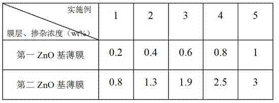
Embodiment 1
[0027] Ensure that the substrate temperature of the sputtering equipment is 100-500 degrees Celsius, argon gas with a flow rate of 100-1000 sccm and oxygen gas with a flow rate of 0-20 sccm are used as reaction gases, and the deposition pressure is controlled at 1.0×10 -3 —8.0×10 -3 between, and then transported into the process chamber of the sputtering equipment to deposit Al-doped Zn0 film, the deposition rate is controlled by adjusting the flow rate and sputtering power, and the targets with different Al doping concentrations are arranged in sequence in the process chamber , the target distribution is 0.5-1 wt%, 1-2 wt%, 2-3 wt% Al-doped Zn0 target, each target has independent power control, the thickness of the three-layer Al-doped Zn0 film 100-200 nanometers, 500-600 nanometers, and 100-250 nanometers, respectively.
Embodiment 2
[0029] Ensure that the substrate temperature of the sputtering equipment is 100-500 degrees Celsius, argon gas with a flow rate of 100-1000 sccm is introduced as the reaction gas, and the deposition pressure is controlled at 1.0×10 -3 —8.0×10 -3 Between, and then transported into the process chamber of the sputtering equipment to deposit Ga-doped Zn0 film, the deposition rate is controlled by adjusting the flow rate and sputtering power, and the targets with different Ga doping concentrations are arranged in sequence in the process chamber , the target distribution is 0.2-0.57 wt%, 0.6-1 wt%, 1-1.5 wt% Ga-doped Zn0 target, each target has independent power control, the thickness of the three-layer Ga-doped Zn0 film They are 50-150 nm, 650-750 nm, and 50-150 nm, respectively.
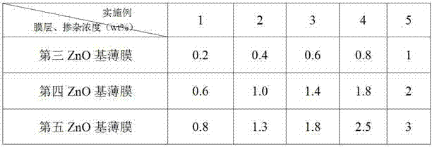
Embodiment 3
[0031] Ensure that the substrate temperature of the sputtering equipment is 100-500 degrees Celsius, argon gas with a flow rate of 100-1000 sccm is introduced as the reaction gas, and the deposition pressure is controlled at 1.0×10 -3 —8.0×10 -3 Between, and then transported into the process chamber of the sputtering equipment to deposit Zr-doped Zn0 film, the deposition rate is controlled by adjusting the flow rate and sputtering power, and the targets with different Zr doping concentrations are arranged in sequence in the process chamber , the target distribution is 0.2-0.5 wt%, 0.5-0.8wt%, 0.8-1.2 wt% Zr-doped Zn0 target, each target has independent power control, the thickness of the three-layer Zr-doped Zn0 film 30-100 nanometers, 600-800 nanometers, and 50-150 nanometers, respectively.
PUM
| Property | Measurement | Unit |
|---|---|---|
| Thickness | aaaaa | aaaaa |
| Thickness | aaaaa | aaaaa |
| Thickness | aaaaa | aaaaa |
Abstract
Description
Claims
Application Information
 - R&D
- Intellectual Property
- Life Sciences
- Materials
- Tech Scout
- Unparalleled Data Quality
- Higher Quality Content
- 60% Fewer Hallucinations
Browse by: Latest US Patents, China's latest patents, Technical Efficacy Thesaurus, Application Domain, Technology Topic, Popular Technical Reports.
© 2025 PatSnap. All rights reserved.Legal|Privacy policy|Modern Slavery Act Transparency Statement|Sitemap|About US| Contact US: help@patsnap.com