Electrically tunable dual-mode dual-passband filter with constant bandwidth

A dual-pass-band filter, constant bandwidth technology, applied in waveguide-type devices, circuits, resonators, etc., can solve the problems of poor performance of tunable filters, large fluctuations in intra-band insertion loss, and narrow tuning range. The effect of improving out-of-band rejection, lowering resonance frequency, and increasing coupling strength

Inactive Publication Date: 2014-06-18
西安伊艾姆科技有限公司
View PDF0 Cites 0 Cited by
  • Summary
  • Abstract
  • Description
  • Claims
  • Application Information

AI Technical Summary

Problems solved by technology

However, in the early stage of research, the performance of tunable filters was very poor. First, the tuning range was very narrow, and second, the passband bandwidth varied with frequency, resulting in large fluctuations in the in-band insertion loss.
[0004] In January 2009, E.E.Djoumessi et al. published "Varactor-tuned quarter-wavelength dual-bandpass filter" in the IET Microwave Antennas Propagation journal (Vol.3, no.1, pp.117–124, 2009), proposing a Electrically tuned dual-passband microstrip filter, which can realize continuous adjustment of two passbands, but the bandwidth decreases as the frequency decreases, and the insertion loss becomes significantly worse; in August 2010, Wenxing Tang et al. published in IEEE Transactions on Microwave Theory and Techniques (vol.58, no.8, pp.2213-2219, 2010) published "Varactor-Tuned Dual-Mode Bandpass Filters", proposing a new type of electronically tuned dual-mode microstrip filter , the filter has only one transmission zero outside the band, and only achieves a single passband continuously adjustable

Method used


Image

  • Electrically tunable dual-mode dual-passband filter with constant bandwidth
  • Electrically tunable dual-mode dual-passband filter with constant bandwidth
  • Electrically tunable dual-mode dual-passband filter with constant bandwidth

Examples


Embodiment Construction

[0023] Embodiments of the present invention are described in detail below in conjunction with accompanying drawings:

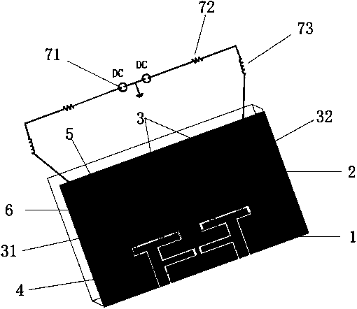
[0024] refer to figure 1 , the present invention mainly consists of a microstrip dielectric substrate 1, a metal ground plate 2, two identical recessed square resonant rings 3 and a pair of input and output coplanar waveguide feeders 4, two varactor diodes 5, ground holes 6 and DC The bias circuit 7 is composed. in:

[0025] The microstrip dielectric substrate 1 adopts double-sided copper-clad laminates, the metal ground plate 2 is under the double-sided copper-clad plates, and the feeder 4 is arranged on the metal ground plate 2, as shown in figure 2 As shown; a resonant ring 3 and a grounding hole 6 are provided on the double-sided copper clad board, and the two same square resonant rings 31 and 32 are in a square ring structure, and the four sides of the square ring are all sunken inwards. A small triangle is cut off at the corner of the part, and the t...


PUM


Abstract

The invention discloses an electrically tunable dual-mode dual-passband filter with constant bandwidth, which mainly solves the problems of great insertion loss, non-constant bandwidth and poor out-of-band rejection performance of an electrically tunable dual-passband filter. The filter comprises a microstrip dielectric substrate (1), a metal grounding plate (2), two square resonant rings (3), a direct-current biasing circuit (7), grounding holes (6) which are arranged in the metal grounding plate, and a pair of input / output feeder lines (4). A folded square resonant ring (31) and a folded square resonant ring (32) are connected by adopting a symmetrical cascade connection method. Variable capacitance diodes (5) are loaded at the internal corners of each square resonant ring. The direct-current biasing circuit (7) is used for providing variable voltage for the variable capacitance diodes (5). The pair of input / output feeder lines (4) adopt F-shaped coplanar waveguide structures and are symmetrically placed above the metal grounding plate (2) to feed power to the square resonant rings (3). The electrically tunable dual-mode dual-passband filter with constant bandwidth has the advantages that the insertion loss can be reduced, the number of out-of-band transmission zero points is increased, the dual-mode dual-passband filter with a continuously tunable first passband and constant bandwidth is realized, and the dual-mode dual-passband filter can be used for wireless communication systems.

Description

technical field [0001] The invention belongs to the technical field of electronic devices, in particular to a microstrip electrically adjustable dual-mode and dual-passband filter, which can be used for a radio frequency front end of a wireless communication system. Background technique [0002] With the rapid development of mobile communication, satellite communication, radar, and remote sensing technology, the wireless spectrum is increasingly crowded, which puts forward very strict requirements on the radio frequency microwave filter in the communication system. Microstrip filters have the advantages of small size, light weight, low cost, and easy processing, and are widely used in microwave circuits. There are various types and realization forms of microstrip filters, and the research of high-performance electrically tunable microstrip filters has always been a hot field. As early as the 1940s, bandpass filters with adjustable frequency appeared. As a special filter, i...

Claims


Application Information

Patent Timeline
Patent Type & Authority Patents(China)
IPC IPC(8): H01P1/203H01P7/00
Inventor 吴边付森杨帅张小艳苏涛龚建强梁昌洪
Owner 西安伊艾姆科技有限公司
Why Eureka
Try Eureka