Medium array antenna

An array antenna and dielectric column technology, which is applied in the field of dielectric array antennas, can solve the problems of high price, difficult processing, complex structure of dielectric rods, etc., and achieve the effects of saving production cost, easy processing and reducing processing difficulty.

Inactive Publication Date: 2012-09-26
SICHUAN UNIV
View PDF3 Cites 9 Cited by
  • Summary
  • Abstract
  • Description
  • Claims
  • Application Information

AI Technical Summary

Problems solved by technology

[0007] Due to the above advantages, dielectric antennas have been extensively studied, and a variety of dielectric antennas with different principles and structures have been developed at home and abroad, such as: Chapter 17 of the authoritative book "Antennas: For All Applications" written by John D. Kraus in the United States Introduced the traditional dielectric rod antenna, which is fed by a cylindrical waveguide, which is not convenient to form an array to obtain higher radiation efficiency; "IEEE TRANSACTIONS ON ANTENNAS AND PROPAGATION" 2010 Volume 58 Issue 12 paper "Design of short axial length high gain dielectric rod antenna" introduces a dielectric antenna made of a special dielectric rod structure. The gain of the antenna can reach 16.7 dBi at the center frequency of 5.6 GHz, but the structure of the dielectric rod in the antenna is complex and difficult to process; " 2ND EUROPEAN CONFERENCE ON ANTENNAS AND PROPAGATION" (EuCAP 2007) paper "Analysis of dielectric resonator antenna arrays with supporting perforated rods" on pages 1 to 5 of "(EuCAP 2007) proposes a dielectric array antenna with perforated rods, which is excited by aperture coupling microstrip lines A parallel-fed array is formed, but the dielectric body radiation element in the antenna adopts a square structure, and the side lobes and back lobes of the antenna are relatively large
In particular, most of the existing dielectric antennas use high dielectric constant dielectrics, which are expensive and are not conducive to the wide application of dielectric antennas.

Method used


Image

  • Medium array antenna
  • Medium array antenna
  • Medium array antenna

Examples


Embodiment

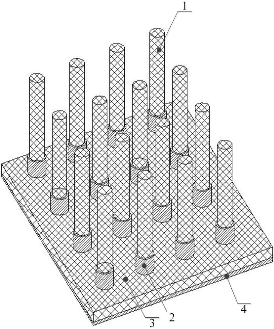
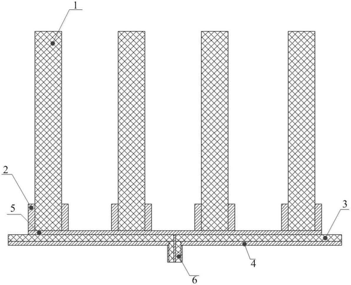
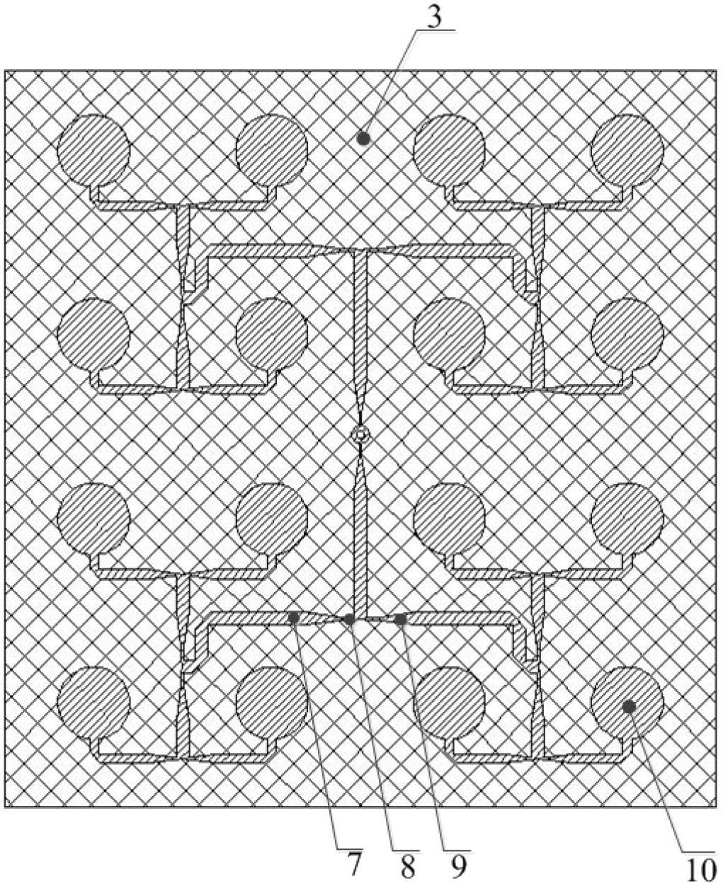
[0029] Such as Figure 1~3 As shown, the dielectric pillar array antenna uses 4×4 cylindrical dielectric pillars 1 as the antenna radiation unit; the height of the dielectric pillars is 80mm, and the radius is 4.4mm. The distance between the centers forms an antenna array; the array antenna uses a microstrip parallel feed network 5 to realize equal-amplitude and in-phase feed to the dielectric column; the microstrip parallel feed network 5 is printed on the dielectric layer 3 of the printed circuit board; the coaxial line 6 The inner conductor passes through the metal formation 4, the dielectric layer 3 is connected to the microstrip parallel feed network 5; the outer conductor of the coaxial line 6 is connected to the metal formation 4; a metal sleeve 2 is installed at the end of each dielectric column, and the metal sleeve is welded on On the circular metal patch 10 , the circular metal patch is printed on the dielectric layer. On the one hand, the metal sleeve fixes the die...


PUM


Abstract

The invention discloses a medium array antenna. The medium array antenna is characterized by adopting dielectric cylinders (1) as an antenna radiation unit; multiple dielectric cylinders (1) are arranged into an antenna array at certain intervals, so as to realize high gain; the array antenna realizes uniform amplitude in-phase feed to the medium columns by adopting a micro-strip parallel feed network (5); the micro-strip parallel feed network (5) is printed on a dielectric layer (3) of a printed circuit board; an inner conductor of a coaxial cable (6) penetrates through a metal layer (4) and the dielectric layer (3) and is connected with the micro-strip parallel feed network (5); an outer conductor of the coaxial cable (6) is connected with the metal layer (4); the tail end of each dielectric cylinder is provide with a metal sleeve (2), each metal sleeve is welded on a round metal patch (10), and the round metal patches are printed on the dielectric layer; on one hand, the metal sleeves are used for fixing the dielectric cylinders; on the other hand, the metal sleeves are used for guiding electromagnetic energy to be spread onto the dielectric cylinders.

Description

technical field [0001] The invention relates to a dielectric array antenna and belongs to the field of antennas in radio equipment. Background technique [0002] Antenna is a key component in radio equipment. It undertakes the function of energy conversion and directional radiation (or reception), directly determines the efficiency of electromagnetic energy transmission in space, and affects the working effect of the entire wireless system. With the rapid development of modern communication technology, higher requirements are put forward for the miniaturization, broadband, and low loss performance of the antenna. Among the existing antenna types, the dielectric antenna has been widely concerned and applied due to its own advantages. The dielectric antenna contains one or more dielectric bodies to form the radiation unit of the antenna. The main advantages are as follows: [0003] 1. Easy to feed, can use a variety of feeding methods, such as coaxial probe feeding, microstr...

Claims


Application Information

Patent Timeline
Patent Type & Authority Applications(China)
IPC IPC(8): H01Q21/00H01Q1/36H01Q1/50
Inventor 陈星黄卡玛郭庆功刘长军赵翔闫丽萍杨晓庆杨阳
Owner SICHUAN UNIV
Why Eureka
Try Eureka