Exhaust gas purification method and exhaust gas purification system for reciprocating internal combustion engine

A technology for exhaust gas purification and internal combustion engines, applied to internal combustion piston engines, combustion engines, exhaust gas treatment, etc., to achieve the effects of improving reduction, promoting reduction reactions, and inhibiting excessive characteristic deterioration

Inactive Publication Date: 2012-09-26
MITSUBISHI HEAVY IND LTD
View PDF7 Cites 7 Cited by
  • Summary
  • Abstract
  • Description
  • Claims
  • Application Information

AI Technical Summary

Problems solved by technology

However, particulate matter (PM: Paticulate Matter) such as unburned fuel contained

Method used


Image

  • Exhaust gas purification method and exhaust gas purification system for reciprocating internal combustion engine
  • Exhaust gas purification method and exhaust gas purification system for reciprocating internal combustion engine
  • Exhaust gas purification method and exhaust gas purification system for reciprocating internal combustion engine

Examples


Embodiment 1)

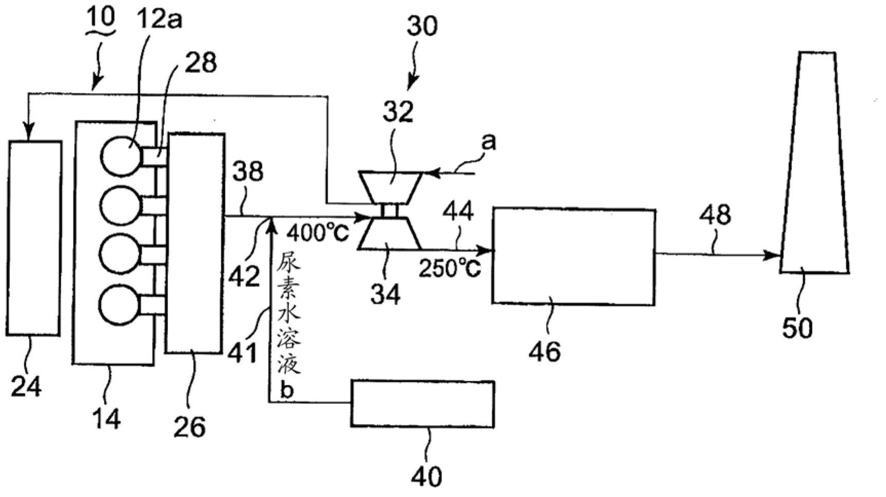
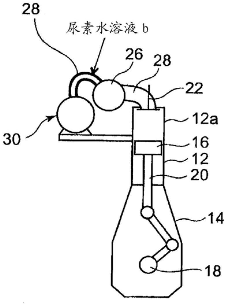
[0051] according to figure 1 and figure 2 The first embodiment of applying the method of the present invention and the system of the present invention to a two-stroke reciprocating marine diesel engine will be described. figure 1 and figure 2 Among them, a two-stroke reciprocating marine diesel engine 10 has a plurality of cylinders 12 , a ventilation chamber 24 and an exhaust manifold 26 . A crank chamber 14 is provided below the cylinder 12 , and a crankshaft 18 is provided in the crank chamber 14 . A piston 16 provided inside the cylinder 12 is connected to a crankshaft 18 via a piston rod 20 .

[0052] A cylinder head 12 a is provided on an upper portion of each cylinder 12 , and each cylinder head 12 a is connected to an exhaust manifold 26 via an exhaust branch pipe 28 . An exhaust valve 22 is provided at the outlet of the cylinder head 12a.

[0053] The compressed air a compressed by the compressor 32 of the supercharger 30 is supplied to the cylinder 12 via th...

Embodiment 2)

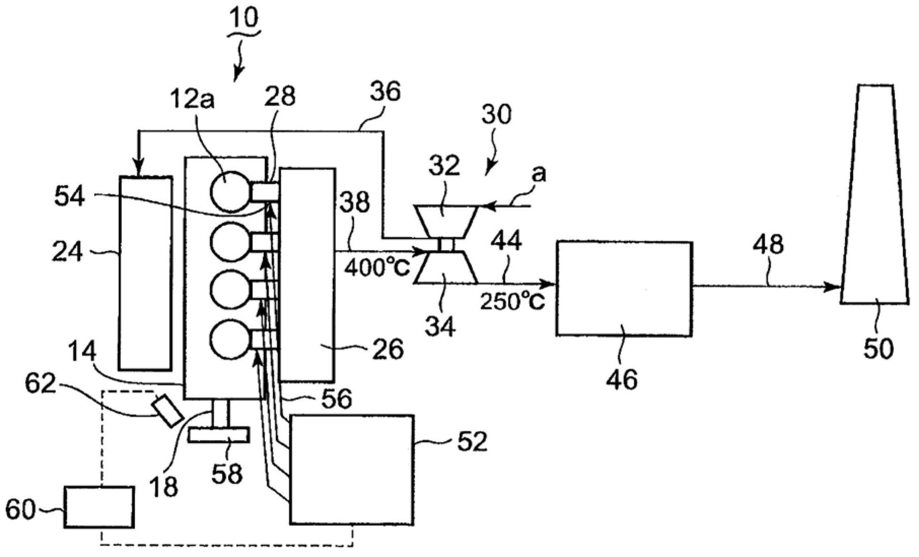
[0060] Next, pass image 3 The second embodiment of the method of the present invention and the system of the present invention will be described. image 3 Among them, a plurality of urea aqueous solution supply units 54 are provided in each of the plurality of exhaust branch pipes 28 . The urea aqueous solution b is supplied from the urea aqueous solution supply device 52 to each urea aqueous solution supply unit 54 via the piping 56 .

[0061] A stabilizer 58 is attached to the crankshaft 18 protruding to the outside of the crank chamber 14 . A crankshaft phase sensor 62 is provided near the crankshaft 18 , and the phase of the crankshaft 18 is detected by detecting a detection mark (not shown) attached to the stabilizer 58 by the crankshaft phase sensor 62 .

[0062] The phase detection signal of the crankshaft phase sensor 62 is sent to the controller 60, and the controller 60 sends a control signal to the urea aqueous solution supply device 52 according to the phase det...

Embodiment 3)

[0068] Next, pass Figure 4 and Figure 5 The third embodiment of the method of the present invention and the system of the present invention will be described. Figure 4The present embodiment is the same as the above-mentioned second embodiment in that the urea aqueous solution supply part 54 is provided in the exhaust branch pipe 28 . The difference from the second embodiment is that a rotation speed sensor 72 for detecting the rotation speed of the crankshaft 18 is provided instead of the crankshaft phase sensor 62 . Furthermore, an exhaust gas temperature sensor 74 for detecting the temperature of exhaust gas flowing through each exhaust branch pipe 28 is provided, and an ammonia concentration sensor 76 is installed in the exhaust gas path 48 downstream of the SCR catalytic converter 46 . Other structures are the same as the second embodiment.

[0069] In this embodiment, as the operating state quantity of the reciprocating marine diesel engine 10 in operation, the rota...


PUM


Abstract

In order to suppress extreme deterioration in the properties of a reciprocating internal combustion engine and enable the removal of NOx in exhaust gas in cases in which the NOx within the exhaust gas of a reciprocating internal combustion engine equipped with a supercharger is removed with an SCR system, a reciprocating marine diesel engine (10) in which a supercharger (30) has been disposed in an exhaust pipe (38, 44, 48) is provided with an aqueous urea solution supply unit (42) in the exhaust pipe (38) upstream of a turbine (34), whereby an aqueous urea solution (b) is supplied from an aqueous urea solution tank (40). The aqueous urea solution (b) is evaporated by the reserved heat of the exhaust gas and is hydrolyzed into ammonia gas. The ammonia gas is uniformly stirred and mixed with the exhaust gas in a highly turbulent flow field of the turbine (34). Thereafter, the ammonia gas deoxidizes the NOx within the exhaust gas in an SCR catalyst converter (46), which is disposed in the exhaust pipe (44) downstream of the supercharger (30), and converts the NOx to nitrogen and water vapor. Since the aqueous urea solution (b) is supplied to the exhaust pipe (38) upstream of the turbine (34), ammonia gas can be generated without installing additional heating equipment such as an auxiliary burner.

Description

technical field [0001] The present invention relates to an exhaust gas purification method and exhaust gas purification system applicable to reciprocating internal combustion engines such as marine diesel engines. Background technique [0002] Diesel engines are widely used for ships, automobiles, etc. in the transportation industry because of their advantages in fuel consumption compared to gasoline engines. However, particulate matter (PM: Paticulate Matter) such as unburned fuel contained in exhaust gas and NO known as nitrogen oxides X (NO, NO 2 ) and so on become a problem. Thus, as the NO from the exhaust X The means of removal is known to use the hydrolysis of urea water to obtain ammonia gas to make the NO contained in the exhaust gas X The method of reductive removal on the catalyst. This method is known as an SCR (Selective Catalytic Reduction: Selective Catalytic Reduction) system. [0003] Patent Document 1 (JP-A-2009-209896) discloses this SCR system. The...

Claims


Application Information

Patent Timeline
IPC IPC(8): F01N3/08F01N3/24F01N3/28F02D45/00
CPCF02D2041/1468F01N2610/1453F02D41/1446Y02T10/24F02B37/00Y02T10/144F01N3/208Y02T10/16F01N2610/02Y02T10/12F01N3/08F01N3/24F01N3/28F02D45/00
Inventor 石田裕幸长船信之介
Owner MITSUBISHI HEAVY IND LTD
Why Eureka
Try Eureka