Scanning type laser vision sensing-based narrow-gap deep-groove automatic laser multilayer welding method for thick plate

A technology of visual sensing and welding method, applied in the field of welding and automatic welding, can solve the problem of low groove setting accuracy, easy to appear shading phenomenon, and can not realize the planning and welding of laser multi-layer welding bead with narrow gap and deep groove. and other problems, to achieve the effect of simple and easy welding process, no blind spots, high flexibility and independence

Inactive Publication Date: 2012-10-03
HARBIN INST OF TECH
View PDF8 Cites 71 Cited by
  • Summary
  • Abstract
  • Description
  • Claims
  • Application Information

AI Technical Summary

Problems solved by technology

[0005] The purpose of the present invention is to solve the problem that the existing welding method based on structured light vision sensing can only be used for simple shallow groove laser seam tracking tasks, and is prone to occurrence of The problem of shadowing phenomenon, low accuracy of groove setting, and real-time weld centering calibration can only be realized, and laser multi-layer welding bead planning and welding of narrow gap and deep groove cannot be realized. A laser automatic multi-layer welding method for thick plate narrow gap deep groove laser automatic multi-layer welding based on scanning laser vision sensor used in conjunction with weld groove information recognition system

Method used


Image

  • Scanning type laser vision sensing-based narrow-gap deep-groove automatic laser multilayer welding method for thick plate
  • Scanning type laser vision sensing-based narrow-gap deep-groove automatic laser multilayer welding method for thick plate
  • Scanning type laser vision sensing-based narrow-gap deep-groove automatic laser multilayer welding method for thick plate

Examples


specific Embodiment approach 1

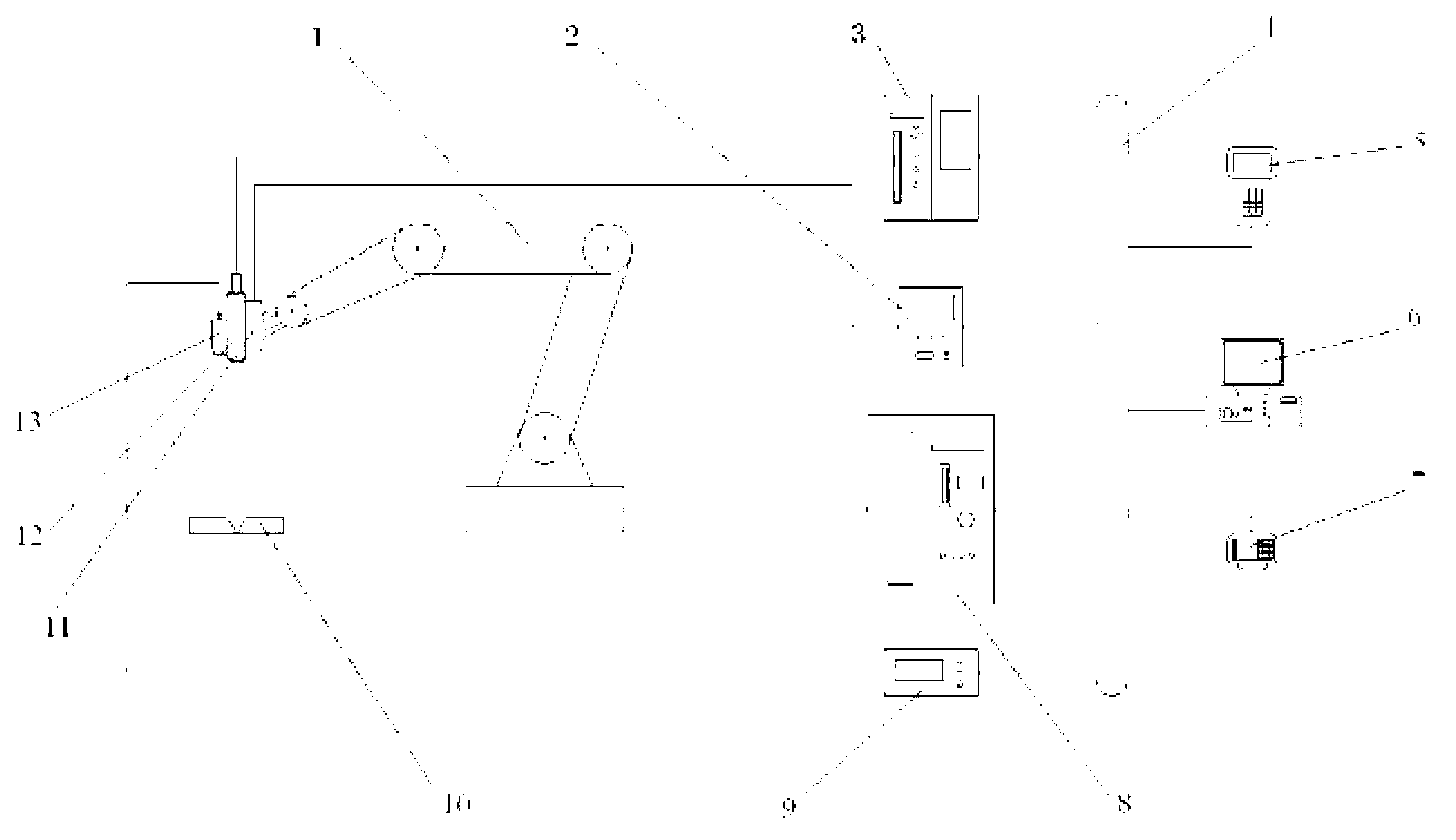
[0027] Specific implementation mode one: combine figure 1 , figure 2 , image 3 , Image 6 with Figure 12 To illustrate this embodiment, the specific steps of the laser automatic multi-layer welding method for thick plate narrow gap deep groove laser automatic multilayer welding based on scanning laser vision sensing in this embodiment are:

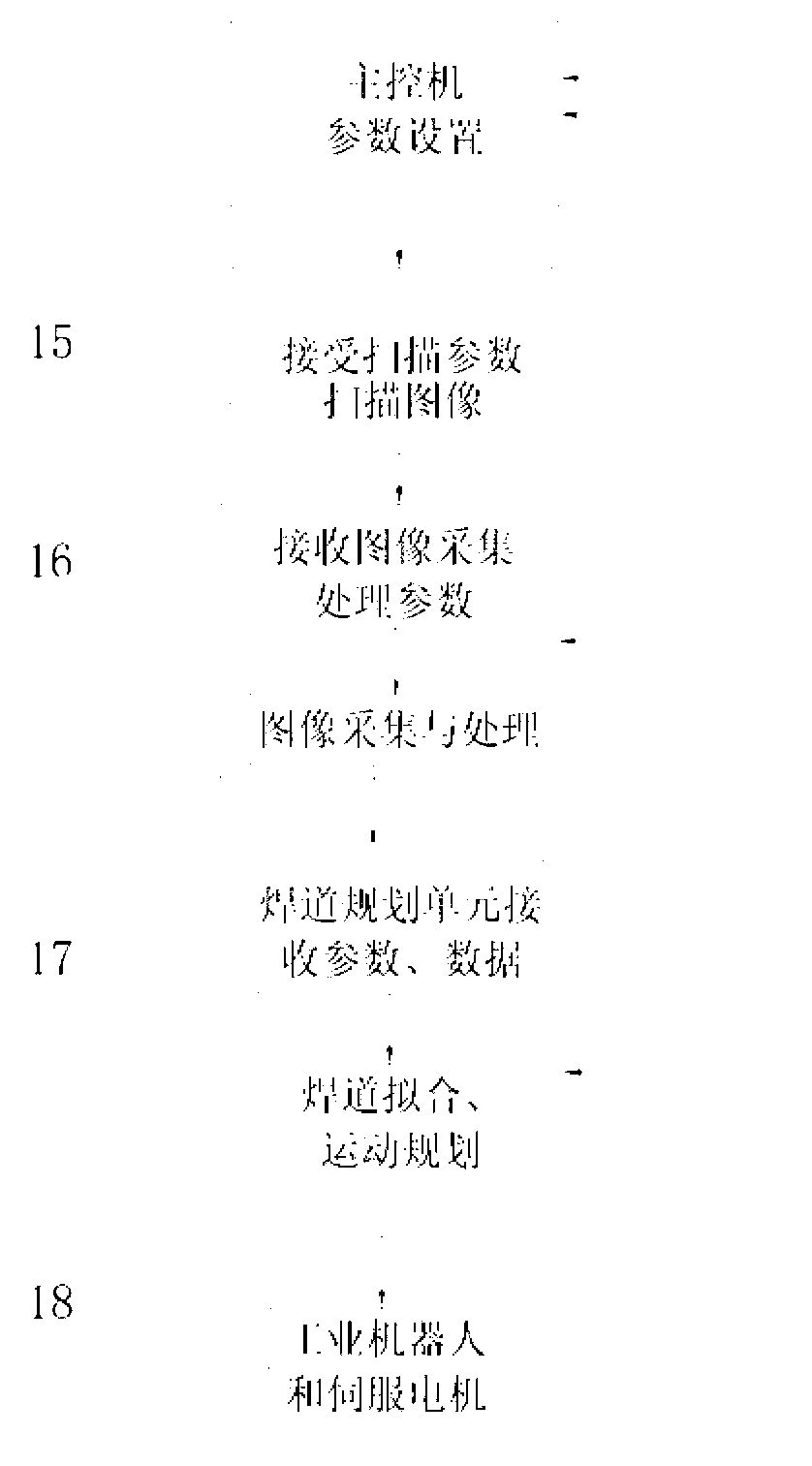
[0028] Step 1. Select the groove form as V-shaped groove, and set parameters through parameter setting and control unit;

[0029] Step 2: The image scanning unit scans the cross-sectional image of the groove of the thick plate workpiece to be welded, and obtains an array of 512 points for each scan, the range of abscissa is 0~511, and the range of ordinate is 1~1024. The coordinates are arranged in sequence, which is the two-dimensional image of the weld groove obtained by this scan;

[0030]Step 3, the image acquisition, processing and calculation unit performs real-time synchronous acquisition of the scanned V-shaped groove cross...

specific Embodiment approach 2

[0051] Specific implementation mode two: combination figure 1 , figure 2 , image 3 , Image 6 and Figure 12 Describe this embodiment. In Step 3 of this embodiment, perform image algorithm processing on the collected groove cross-section image to obtain weld image data. The specific process is: (1) Perform five-point centering on the collected groove cross-section image Value filtering denoising algorithm to process the filtered image, (2), use the slope-intercept algorithm to extract the feature points on the filtered image, first: first traverse all points on the filtered V-shaped cross-sectional image and find the lowest point , which is the first feature point b of the weld. Connect point b to coordinate point n on the Y axis corresponding to coordinate point 0 on the X axis of the two-dimensional coordinate system to form a straight line with a slope of K bn =(y b -y n ) / x b , through all points on the filtered image between point b and point n, make a straight l...

specific Embodiment approach 3

[0055] Specific implementation mode three: combination Image 6 and Figure 12 Describe this embodiment, in step 4 of this embodiment, the multi-layer welding bead planning unit performs the approximate simplification of the multi-layer welding bead to an equal area according to the characteristic parameters obtained by the image acquisition, processing and calculation unit and the preset number of weld layers The trapezoidal fitting calculation, the fitting algorithm is: weld bead feature point extraction, from the second feature point a and the third feature point c on the V-shaped cross-sectional image to the current weld bead collected by the acquisition unit between the two Traversing the points on the image, finding the two lowest points in the current weld bead are the first feature point i1 of the weld bead and the second feature point k1 of the weld bead, and then traversing the points between i1 and k1 to find the highest point among them, namely is the third featur...


PUM

PropertyMeasurementUnit
wavelengthaaaaaaaaaa

Abstract

The invention discloses a scanning type laser vision sensing-based narrow-gap deep-groove automatic laser multilayer welding method for a thick plate, relates to a welding method, and aims to solve the problems that the conventional structured light vision sensing-based welding method can only be used for a simple shallow-groove laser weld seam tracking task and that when the conventional structured light vision sensing-based welding method is used for the narrow-gap deep-groove weld seam welding of the thick plate, a covering phenomenon is easily produced, the groove identification accuracy is lower, only real-time weld seam alignment calibration can be realized and narrow-gap deep-groove laser multilayer welding bead planning and welding cannot be realized. The method specifically comprises the following steps of: 1, selecting a groove form; 2, scanning a groove section image of a thick plate workpiece to be welded by using an image scanning unit; 3, processing the acquired groove section image by using an image algorithm to obtain weld seam image data; 4, performing fitting calculation; and 5, finishing the welding of welding beads layer by layer. The method is used for the deep-groove weld seam welding of the thick plate.

Description

technical field [0001] The invention relates to a welding method, in particular to a laser automatic welding method based on scanning laser vision sensing for real-time tracking and welding bead planning of thick plate narrow gap deep groove multi-layer welding, belonging to the field of automatic welding. Background technique [0002] At present, laser and laser-arc hybrid welding have been widely used in thick plate deep groove welding production industry as efficient welding methods, and path planning and motion control are often carried out by welding machine tools or robot teaching or offline programming. In the actual laser multi-layer welding of thick plates, due to the influence of factors such as thermal deformation and thermal stress, each welding seam needs to be taught or programmed again to ensure the accuracy of the position of the welding torch relative to the workpiece and the attitude of the welding torch (defocus amount) , causing the adjustment time to be ...

Claims


Application Information

Patent Timeline
Patent Type & Authority Applications(China)
IPC IPC(8): B23K26/20B23K26/42B23K26/03B23K26/24
Inventor 雷正龙陈彦宾陈宏李俐群
Owner HARBIN INST OF TECH
Why Eureka
Try Eureka