
Solid-liquid separation device for organic carbon sources in excess sludge

A technology for separation of excess sludge and solid-liquid, applied in sludge treatment, biological sludge treatment, water/sludge/sewage treatment, etc., can solve problems such as limited separation capacity and influence on downstream microbial operation, and achieve the goal of reducing clogging Effect

Active Publication Date: 2012-10-03
TSINGHUA UNIV
View PDF6 Cites 6 Cited by
  • Summary
  • Abstract
  • Description
  • Claims
  • Application Information

AI Technical Summary

Problems solved by technology

[0003] At present, the most commonly used mud-water separation technologies at home and abroad mainly include: belt filter press, plate-and-frame filter press and centrifuge, etc., but these methods are limited by the separation capacity of the equipment during operation, and it is inevitable that The entry of anaerobic microorganisms, which will affect the operation of downstream microorganisms to synthesize PHA
[0004] At present, the carbon source used for PHA synthesis mainly comes from the fermentation of grain crops such as corn and wheat. The synthesis of PHA by using excess sludge hydrolysis carbon source can save a lot of food, but the concentration of carbon source obtained after anaerobic hydrolysis treatment is far less than that of grain The carbon source concentration produced by fermentation, so for the synthesis of PHA with low carbon source concentration, a continuous fermentation device must be used, that is, the sludge hydrolyzate used as the medium must be continuously supplied

Method used


Image

  • Solid-liquid separation device for organic carbon sources in excess sludge

Examples


Embodiment Construction

[0029] The experimental methods used in the following examples are conventional methods unless otherwise specified.

[0030] The materials and reagents used in the following examples can be obtained from commercial sources unless otherwise specified.

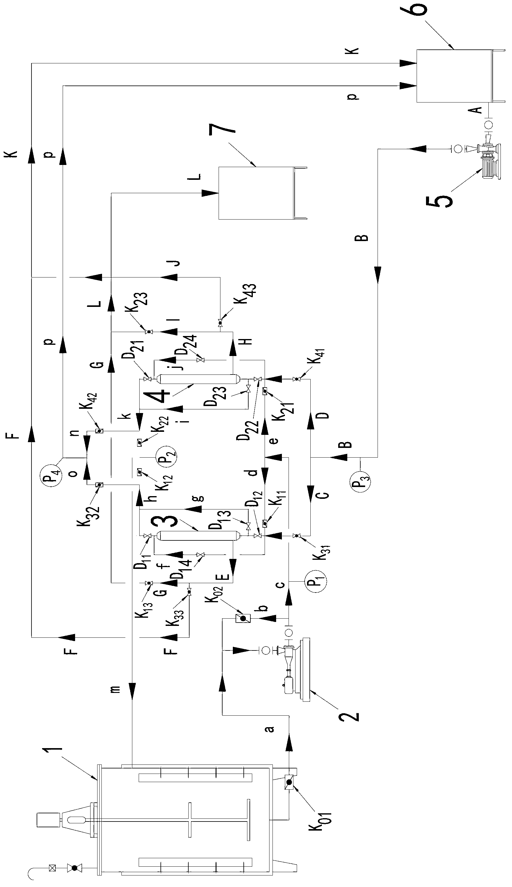
[0031] Such as figure 1 As shown, the surplus sludge organic carbon source solid-liquid separation device provided by the present invention comprises anaerobic hydrolysis reactor 1, screw pump 2, chemical cleaning tank 6, chemical cleaning pump 5, ceramic membrane microfiltration device I3 and ceramic membrane microfiltration Device II4;

[0032] The bottom of the anaerobic hydrolysis reactor 1 is connected to the screw pump 2 through the excess sludge pipeline a, and the excess sludge pipeline a is equipped with a ceramic membrane operating valve K 01 ; The screw pump 2 communicates with the ceramic membrane microfiltration device I3 and the ceramic membrane microfiltration device II4 through the excess sludge pipeline b, c, ...


PUM


Abstract

The invention discloses a solid-liquid separation device for organic carbon sources in excess sludge. The solid-liquid separation device comprises an anaerobic hydrolysis reactor, a screw pump, a chemical cleaning tank, a chemical cleaning pump, a ceramic membrane microfiltration device I, a ceramic membrane microfiltration device II and a carbon source storage tank; the bottom of the anaerobic hydrolysis reactor is communicated with the screw pump; the outlet of the screw pump is communicated with the ceramic membrane microfiltration device I and the ceramic membrane microfiltration device II respectively; the chemical cleaning tank is communicated with the chemical cleaning pump; the outlet of the chemical cleaning pump is communicated with the ceramic membrane microfiltration device I and the ceramic membrane microfiltration device II respectively; and both the ceramic membrane microfiltration device I and the ceramic membrane microfiltration device II are communicated with the carbon source storage tank through hydrolyzed filtrate pipelines. Through the solid-liquid separation device, the dissoluble organic carbon sources can be effectively eluted, so that hydrolysis and acidification of the sludge are promoted; membrane channel blockage can be controlled and reduced in double flow directions, and continuous operation is realized; and a high solid-liquid separation effect is achieved, and the concentration of effluent microbes is less than 100 microbes per milliliter.

Description

technical field [0001] The invention relates to a solid-liquid separation device for excess sludge organic carbon source, which belongs to the technical field of environmental protection equipment. Background technique [0002] After anaerobic hydrolysis of the remaining sludge from urban sewage treatment plants, there are a large amount of recyclable organic carbon sources in the mud-water mixture, which can be used as additional carbon sources for nitrogen and phosphorus removal, synthesis of biodegradable plastics (PHA ), biogas and electricity production. Among them, due to the high added value of PHA, the synthesis of PHA by using excess sludge carbon source has attracted the attention of researchers at home and abroad. [0003] At present, the most commonly used mud-water separation technologies at home and abroad mainly include: belt filter press, plate-and-frame filter press and centrifuge, etc., but these methods are limited by the separation capacity of the equipm...

Claims


Application Information

Patent Timeline
IPC IPC(8): C02F11/00C02F11/04C02F11/12
Inventor 施汉昌王慧熊惠磊王青
Owner TSINGHUA UNIV
Learn More