Biomass gas generation system

A biomass gas generation system technology, applied in the manufacture of combustible gas, educts, petroleum industry, etc., can solve the problems of tar easily blocking pipelines and switches, secondary pollution, waste residue, tar water chaos and other problems

Active Publication Date: 2012-10-03
无锡湖光工业炉有限公司
View PDF6 Cites 16 Cited by
  • Summary
  • Abstract
  • Description
  • Claims
  • Application Information

AI Technical Summary

Problems solved by technology

[0004] Biomass gasifier is a commonly used biomass gas production equipment, but the current biomass gasifier is still in its infancy. Some small gasifiers are easy to block pipes and switches with tar when they are in use, and emit odors when they are used. At the same time, due to The users of small gasifiers are relatively scattered, and the waste residue and tar water produced by them are dumped indiscriminately, causing secondary pollution

Method used


Image

  • Biomass gas generation system
  • Biomass gas generation system
  • Biomass gas generation system

Examples


Embodiment Construction

[0070] The present invention will be further described below in conjunction with specific drawings and embodiments.

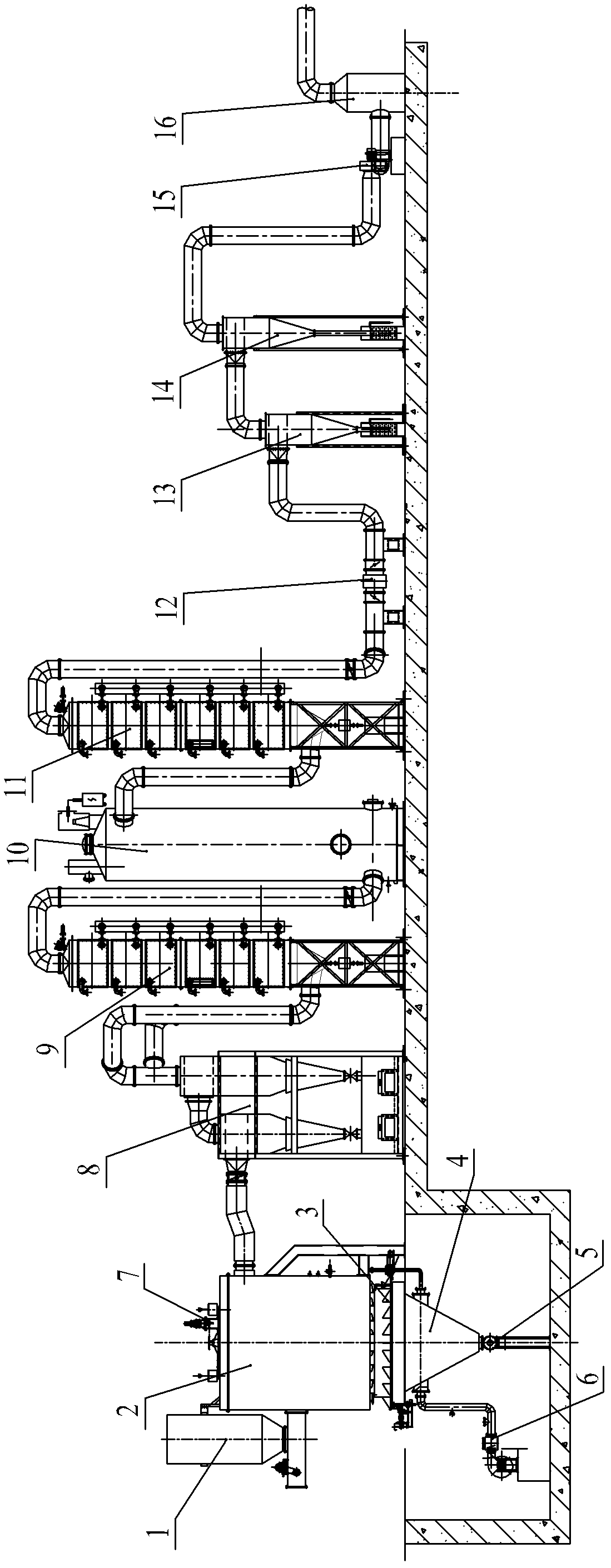
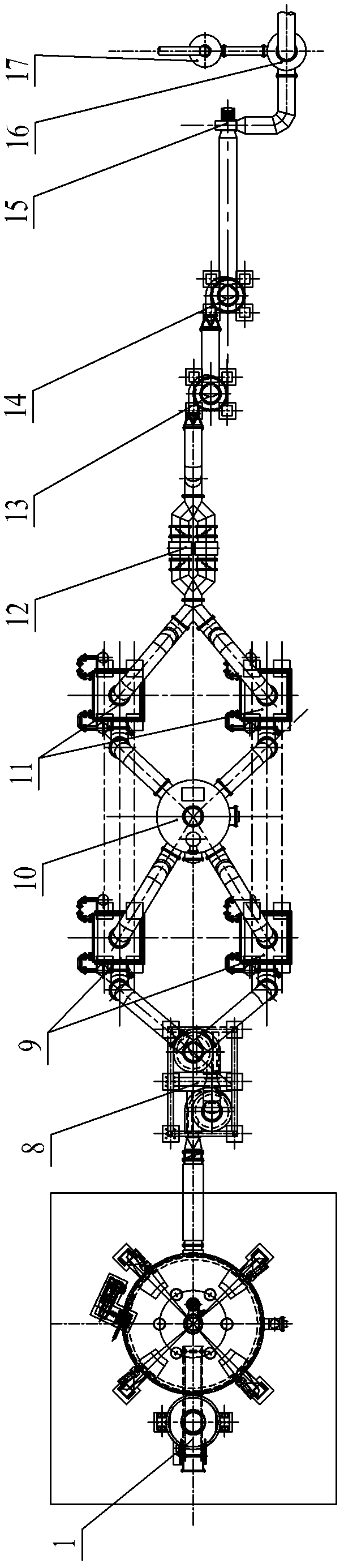
[0071] The biomass gas generation system in the embodiment mainly includes a feed device 1, a biomass gasifier, a post-processing system, and a gas transmission and storage pipeline system, which are connected in sequence according to the sequence of gas generation and treatment. The biomass gasifier It has a fuel inlet and a gas outlet, the combustion inlet is connected to the feed device 1, and the gas outlet is connected to the post-processing system through a connecting pipe; the post-processing system includes a cyclone dust removal device 8, a first-stage tubular intercooler 9, and an electric tar catcher. device 10, secondary tube-type intercooler 11, filtration and purification device 12, primary water-gas separator 13 and secondary water-gas separator 14, and the inlet of cyclone dust removal device 8 passes through connecting pipe fittings and the fuel...


PUM

PropertyMeasurementUnit
diameteraaaaaaaaaa
thicknessaaaaaaaaaa
heightaaaaaaaaaa

Abstract

The invention relates to a biomass gas generation system. The system comprises a feed device, a biomass gasification furnace, a post-treatment system and a gas transmission and storage pipeline system which are connected in a sequence of gas generation and treatment, wherein the biomass gasification furnace is provided with a fuel inlet and a gas outlet, the fuel inlet is connected with the feed device, and the gas outlet is communicated with the post-treatment system through a connecting pipe fitting; and the post-treatment system comprises a cyclone dust collector, a primary pipe-type intercooler, an electrical tar precipitator, a secondary pipe-type intercooler, a filter and purification device, a primary water-steam separator and a secondary water-steam separator. The biomass gas generation system has a smart and reasonable structure, cannot cause secondary pollution to the surrounding environment while biomass energy is reasonably utilized; and prepared gas can be applied to civil use instead of the conventional stove or liquefied gas, and can be applied to the industrial field, such as directly being used as industrial gas or being used for supplying power generation for power generation equipment.

Description

technical field [0001] The invention belongs to the technical field of biomass gas production equipment, and in particular relates to a biomass gas generation system. Background technique [0002] With the rapid development of industry and the rapid advancement of urbanization, energy shortages and environmental pollution have become the focus of attention in today's society. In rural areas, the phenomenon of burning straw and using old-fashioned wood stoves already exists, which also emits a large amount of dust and warm gases. At present, biomass energy waste is mainly agricultural waste, a large part of which can be used as energy. In addition, most of forestry and wood processing waste can also be used as energy. [0003] Biomass gas produced by biomass gasifier belongs to green new energy, which has strong vitality. Since the raw materials of biomass gas are crop stalks, forest wastes, edible mushroom residues, cattle, sheep and livestock dung and all combustible sub...

Claims


Application Information

Patent Timeline
Patent Type & Authority Applications(China)
IPC IPC(8): C10J3/20C10J3/72C10J3/74C10J3/84
CPCY02P20/145
Inventor 徐欢
Owner 无锡湖光工业炉有限公司
Why Eureka
Try Eureka