Treating system, separating apparatus and treating method for oily sludge

A technology for separating equipment and sludge, applied in sludge treatment, water/sludge/sewage treatment, dehydration/drying/concentrated sludge treatment, etc., can solve the problems of difficult production, secondary pollution, high cost, and achieve Avoid uneven mixing, expand application range, and meet emission standards

Pending Publication Date: 2017-05-10
仇霞霞
View PDF5 Cites 17 Cited by
  • Summary
  • Abstract
  • Description
  • Claims
  • Application Information

AI Technical Summary

Problems solved by technology

However, its core technology is a high-speed centrifugal three-phase separation device, which is basically monopolized by countries such as Europe and the United States. It is still difficult for China to produce such devices
Disadvantages of tempering-separation technology: due to the variety of oily sludge, the combination of existing dehydration machinery and agents is not universally applicable
However, this method is only suitable for crude oil recovery and treatment of ground crude oil and oil sands with high oil conte

Method used


Image

  • Treating system, separating apparatus and treating method for oily sludge
  • Treating system, separating apparatus and treating method for oily sludge

Examples


Example Embodiment

[0062] Example 1

[0063] Reference Figure 1-2 The present invention is further illustrated through the following examples.

[0064] Take the oil sludge at the bottom of an oil tank (the sludge contains 30 wt% oil, 35 wt% water, and the rest is solid matter) as an example to illustrate specific embodiments of the present invention.

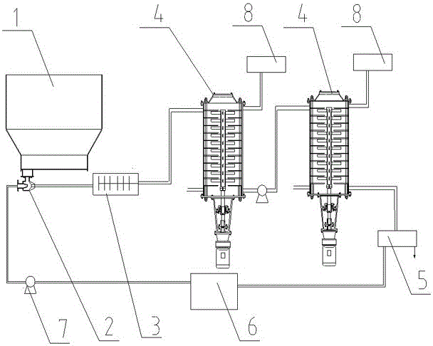
[0065] (1) The treatment method also includes the step of pretreatment of oily sludge. The pretreatment step includes: removing impurities in the oily sludge, then crushing and mixing with water to make a mud-water mixture, and then transporting it to the sludge Storage device 1.

[0066] (2) The jet 2 sucks out the sludge and sprays it into the high-speed crushing device 3 for impact crushing and high-speed shredding. The water source of the jet 2 uses the water in the water storage device 6 (temperature 80℃), and the high-speed crushing device 3 The sludge particles are further broken by high-speed rotation, so that the sludge is completely broken, a...

Example Embodiment

[0070] Example 2

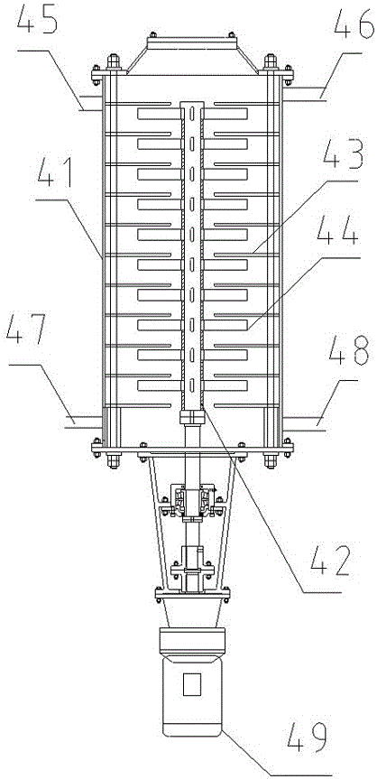
[0071] As another embodiment of the present invention, it is basically the same as the processing method of embodiment 1, but the difference is: in step (3), an extractant is introduced into the feed port 47 at the bottom of the separation device, and the extractant is toluene. The amount of extractant is 0.5wt% of oily sludge. The final oil recovery rate was 98.3%, and the residual oil rate was 1.7%.


PUM

PropertyMeasurementUnit
Granularityaaaaaaaaaa

Abstract

The invention discloses a treating system, separating apparatus and treating method for oily sludge. The separating apparatus comprises a stirring drum, a first drive unit, a stirring shaft, multiple layers of separator plates and stirring members, wherein the stirring shaft is arranged in the stirring drum; the multiple layers of separator plates divide the stirring drum into multiple layers of space; each of the multiple layers of space is provided with one stirring member which is connected with the stirring shaft; the upper part of the stirring drum is provided with a sludge inlet and first floating oil discharge outlet; the lower part of the stirring drum is provided with a sludge outlet; and the bottom or lower part of the stirring drum is provided with a feed inlet for one or more selected from a group consisting of an extractant, air-dissolved water and solid foam particles. The treating system is applicable to dehydration of a variety of oily sludge, enables the oil content of oily sludge to be decreased to 3% or below, can maximally recover oil and does not produce secondary pollution like waste water.

Description

Technical field [0001] The invention relates to a processing system for oily sludge and its separation equipment and processing method. Background technique [0002] Oil sludge mainly refers to the oily sludge formed by crude oil or other oil products and mud due to various reasons, as well as the oily sludge brought out by the system during the normal production of oil fields. It is a solid waste rich in mineral oil. The ingredients are crude oil, mud and water. The size of solid particles can vary from less than micrometers to several inches. The composition of the oil depends on the type of crude oil, refinery structure and operating conditions. The composition of sludge may change over time. Usually sludge contains certain crude oil, heavy metal ions (such as iron, copper, nickel, etc.) and inorganic salt compounds. These sludges generally contain benzene series, phenols and other substances, and are accompanied by foul smell and toxicity. If they come into direct contact w...

Claims


Application Information

Patent Timeline
IPC IPC(8): C02F11/00C02F11/12C10G1/04C10G1/00B02C21/00B02C4/08B02C18/14B07B1/28
CPCC10G1/00C10G1/045C02F11/00C02F11/127B02C4/08B02C18/144B02C21/00B07B1/28C02F2101/32C02F2103/10C02F2303/06C02F2103/365C10G2300/1003
Inventor 仇霞霞李艺凡冷增冰
Owner 仇霞霞
Why Eureka
Try Eureka