Numerical control equipment

A technology of numerical control equipment and wizards, applied in metal processing equipment, large fixed members, driving devices, etc., can solve the problems of complex processing, and achieve the effect of improving processing efficiency, reducing equipment, improving displacement sensitivity and workpiece processing accuracy

Active Publication Date: 2012-10-10
广东省仁丰五金电器有限公司
View PDF10 Cites 4 Cited by
  • Summary
  • Abstract
  • Description
  • Claims
  • Application Information

AI Technical Summary

Problems solved by technology

Although this solution discloses that the problem of electrical connection with the electrode fixture installed on the rotating shaft and rotating with the rotating shaft is solved through the feeding brush and the feeding shaft, the problem it solves is the problem of using a direct drive motor for electric discharge machining, and It is not that the workbench installed on the base does not move, and the five-axis motion CNC machine tool is used to process complex parts, especially the complex processing of five-axis motion turning, turning and milling complex parts

Method used


Image

  • Numerical control equipment
  • Numerical control equipment
  • Numerical control equipment

Examples


Embodiment 1

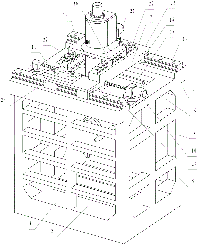
[0052] like Figure 1 to Figure 4 As shown, a CNC machine tool includes an integrally formed main body frame 1 and a worktable 2 . The main frame 1 includes a square base 3, which is integrally formed with the base 3 and is provided at four corner positions of the base 3 and a main support column 4 which is respectively arranged at the middle position of the left, right and rear sides of the base, and is connected to the main support column 4. The horizontal connecting column 5 between them. The main support frame 6 is integrally formed with the main support column 4 and provided on the main support column 4 . The main support frame 6 is a square closed-loop structure with an opening facing the vertical direction.

[0053] The X-direction slide 7 is also included. Between the main support frame 6 and the X-direction sliding seat 7, there are mutually matched X forward guide rails and X backward guide rails. The X-direction sliding seat 7 can slide back and forth along the ...

Embodiment 2

[0066] like Figure 5 to Figure 7 As shown, the difference from Embodiment 1 is that the Y-direction sliding seat 70 includes a Y-direction sliding seat bottom plate 71, an upper convex portion 72 protruding vertically upward from the Y-direction sliding seat bottom plate 71, and a Y-direction sliding seat bottom plate 71 vertically upward The lower protruding portion 73 is provided downwardly. A fixing plane 74 is provided on the outer surfaces of the upper convex portion 72 and the lower convex portion 73 , and a side convex portion 75 is provided on the fixing plane 74 . The outer periphery of the Y-direction sliding seat bottom plate 71 is square, and the upper convex portion 72 and the lower convex portion 73 are protruded from the periphery. A round hole 78 and a square hole 79 are provided in the Y-direction sliding seat 70 penetrating the upper convex part 72 , the Y-direction sliding seat bottom plate 71 , and the lower convex part 73 . The diameter is larger than t...

Embodiment 3

[0069] like Figure 8 As shown, the difference from Embodiment 2 is that the Y-direction sliding seat 120 includes a Y-direction sliding seat bottom plate 121, a cylindrical upper guide sleeve 122 protruding vertically upward from the Y-direction sliding seat bottom plate 121, 121 is a circular tube-shaped lower guide sleeve 123 protruding vertically downward, the outer circumference of the Y-direction sliding seat bottom plate 121 is square, and the circular tube-shaped upper guide sleeve 122 and the circular tube-shaped lower guide sleeve 123 protrude from the periphery.

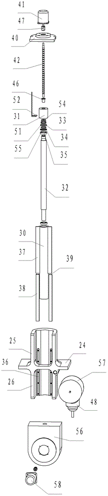
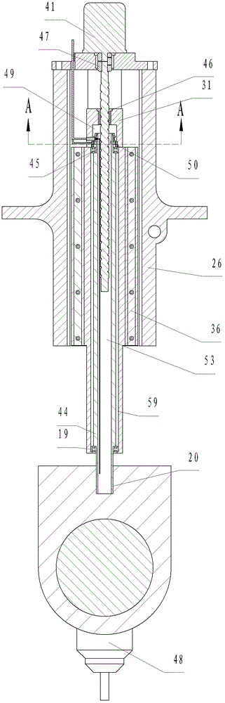
[0070] The main shaft device includes a cylindrical Z guide rod 126 that can move up and down, an end cover 127, a shaft 128 installed in the Z guide rod 126 and only rotatable relative to the Z guide rod 126, a bearing 132, a bearing 131, an external thread nut 134, a drive The first rotor 129 and the first stator 130 rotated by the rotating shaft 128 , the internal thread nut 135 , the Z-direction drivin...


PUM


Abstract

Numerical control equipment comprises a spindle device, a slide seat, a slide seat driving device, a workpiece clamping device and a main processing head, wherein Z-direction guide rod is mounted together with the slide seat only in a up-and-down moving manner; a rotating shaft is arranged in the Z-direction guide rod and can only rotate relative to the Z-direction guide rod; a Z-direction screw rod nut is fixed with the Z-direction guide rod; a conducting ring is arranged on the circumference of the rotating shaft; an electric wire accommodating hole or electric wire accommodating groove communicated with the conducting ring is formed in the rotating shaft; an electric wire is accommodated in the electric wire accommodating hole or electric wire accommodating groove; a swinging seat is formed integrally or fixed at the lower end of the rotating shaft; one end of the electric wire is electrically connected with the conducting ring; the other end of the electric wire is electrically connected with a main processing head driving motor and a swing shaft driving device which are mounted on the rotating shaft; the conducting ring is in triboelectric connection with an electric brush electrically connected an external power supply; and the electric brush is fixed with the Z-direction guide rod. The numerical control equipment has the advantages that the rotating shaft can rotate continuously by 360 degrees, and the electric wire connected with a main shaft motor and a rotating shaft driving device is prevented from being twisted off.

Description

technical field [0001] The invention relates to numerical control equipment, in particular to numerical control machine tools of main processing heads, numerical control painting equipment, numerical control welding equipment, numerical control laser cutting equipment, numerical control laser welding equipment, numerical control plasma cutting equipment, numerical control screw mounting equipment, numerical control gas cutting equipment Wait. Background technique [0002] Existing CNC equipment, in order to process complex parts, generally requires five-axis motion processing, that is, X-axis, Y-axis, Z-axis back-and-forth motion processing, the pendulum axis rotates within a certain angle, and the rotating shaft or worktable rotates 360° continuously. sports. [0003] However, the existing CNC equipment, one is the pendulum shaft installed with the processing head (also known as the universal processing head in the industry), although the pendulum shaft can swing a certain...

Claims


Application Information

Patent Timeline
Patent Type & Authority Applications(China)
IPC IPC(8): B23Q37/00B23Q1/26B23Q5/40
CPCB23Q5/28B23Q1/015B23Q5/02B23Q1/0009B23Q5/40B23Q1/01B23Q1/012B23Q5/36
Inventor 杨东佐
Owner 广东省仁丰五金电器有限公司
Why Eureka
Try Eureka