Internally partitioned gravity-assisted heat pipe heat transfer mechanism

A technology of gravity heat pipe and internal separation, which is applied in the direction of indirect heat exchangers, lighting and heating equipment, etc., can solve the problems of slow start-up time of heat pipes, complex structure, and long heating time of materials, so as to shorten the operation process time and improve heat transfer efficiency High, easy to manufacture effect

Active Publication Date: 2013-08-28
何其伦 +1
View PDF5 Cites 0 Cited by
  • Summary
  • Abstract
  • Description
  • Claims
  • Application Information

AI Technical Summary

Problems solved by technology

The disadvantage of gravity heat pipes in plate shape or shapes other than tubes is that since the heat pipe cavity is integrated, the working medium at the evaporating end absorbs external heat energy, and at the same time it is in contact with the evaporating end of the device and passes through it. Dissipate heat to the material in the equipment, making it difficult for the working medium to quickly reach the evaporation temperature and evaporate. The start-up time of the heat pipe is very slow, and the material heating time is long, which prolongs the processing time
[0005] There is also a separate heat pipe, which is characterized by separating the evaporating end and the condensing end of the heat pipe, and connecting the upper part of the condensing end through the steam pipe on the upper part of the evaporating end, and the lower part of the condensing end The reflux pipe is connected to the lower part of the evaporating end, and the whole system is evacuated into a high vacuum and filled with working fluid, thus forming a separate heat pipe, which greatly improves the start-up time of the heat pipe, but its structure is relatively complicated, and the evaporating end needs to occupy additional space, and the equipment volume increase, making it more difficult

Method used


Image

  • Internally partitioned gravity-assisted heat pipe heat transfer mechanism

Examples


Embodiment Construction

[0017] The present invention will be further described below in conjunction with the accompanying drawings and typical embodiments.

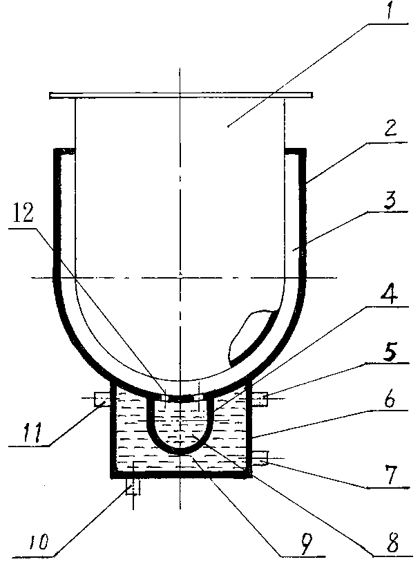
[0018] exist figure 1 Among them, the present invention includes a heating source and a heat pipe. The heating source includes a water tank 6 and a heat supply source arranged in the water tank. The heat pipe includes a heat pipe evaporation end 4 and a heat pipe condensation end cavity 3; the heat pipe evaporation end 4 A heat transfer medium 8 is arranged in the middle; the heat pipe evaporation end 4 is placed in a water tank 6, and there is circulating heating water 9 in the water tank 6, and the water tank 6 includes a circulating water inlet 7, a circulating water outlet 11, and a water tank exhaust Port 5 and sewage outlet 10; the heat pipe condensation end is arranged on the outer wall of the equipment cylinder 1, including the heat pipe condensation end cavity wall 2 and the heat pipe condensation end cavity 3; the heat pipe evaporatio...


PUM


Abstract

The invention aims to provide an internally partitioned gravity-assisted heat pipe heat transfer mechanism which has the advantages of high heat transfer efficiency, little energy consumption, simple structure and small size and can shorten the time of the equipment heating process. The internally partitioned gravity-assisted heat pipe heat transfer mechanism comprises a heating source and a heatpipe, the heat source comprises a water tank and a heat supply source arranged in the water tank, and the heat pipe comprises a heat pipe evaporation end and a heat pipe condensation end; heat transfer medium is arranged in the heat pipe evaporation end; the heat pipe evaporation end is arranged in the water of the water tank, and the water tank comprises a circulating water inlet, a circulating water outlet, a water tank exhaust outlet and a drain outlet; the internally partitioned gravity-assisted heat pipe heat transfer mechanism is characterized in that the heat pipe condensation end is arranged on the outer wall of an equipment barrel and comprises a heat pipe condensation end cavity wall and a heat pipe condensation end cavity; the heat pipe evaporation end is located on the bottom of the heat pipe condensation end and partitioned from the heat pipe condensation end, and the bottom of the heat pipe condensation end is provided with a plurality of through holes, so that the heat pipe evaporation end communicates with the heat pipe condensation end.

Description

technical field [0001] The invention relates to a heating device, in particular to a heat transfer mechanism of an internally separated gravity heat pipe. Background technique [0002] The heat pipe is a heat transfer element with high thermal conductivity, which transfers heat through the phase change of the working medium in the pipe. A typical heat pipe is composed of a tube shell, a liquid-absorbing core and an end cap. After the heat pipe is pumped into a high vacuum, it is filled with an appropriate amount of working fluid. One end of the tube is the evaporating section, and the other end is the condensing section, and an adiabatic section can be arranged between the two sections according to application requirements. When one section of the heat pipe is heated, the working fluid absorbs the latent heat of vaporization and evaporates, and the steam flows to the other end through the capillary wick under a small pressure difference, releasing the latent heat of vapori...

Claims


Application Information

Patent Timeline
Patent Type & Authority Patents(China)
IPC IPC(8): F28D15/02
Inventor 不公告发明人
Owner 何其伦
Why Eureka
Try Eureka