Differential movable type transverse electrode electrostatic precipitator

A transverse electrode and electrostatic precipitator technology, applied in the field of electrostatic precipitators, can solve the problems of unsatisfactory discharge, shrinking dust collection area, and inability to use products to meet standards, etc. The effect of secondary flying

Inactive Publication Date: 2012-10-17
江保祥
View PDF5 Cites 7 Cited by
  • Summary
  • Abstract
  • Description
  • Claims
  • Application Information

AI Technical Summary

Problems solved by technology

[0004] One is the improvement of national standards, which makes the design standard of the electrostatic precipitator that meets the standard discharge lower than the current standard, and cannot meet the discharge standard;
[0005] Second, the complexity of working conditions in various industries (mainly due to the increase in specific resistance caused by changes in kiln raw materials) has changed the original design parameters (worsened working conditions), resulting in a larger selection of the original approach speed and a relatively large dust collection area. Shrunken, the dust collector cannot meet the discharge standard;
[0006] Third, due to the popularization of conventional electrostatic precipitator technology in recent years, in order to squeeze into the electric precipitator industry, some small manufacturers have slapped prices on each other, viciously competed, and arbitrarily selected the driving speed without considering the nature of the dust, greatly reducing the dust collection area and circulatio

Method used


Image

  • Differential movable type transverse electrode electrostatic precipitator
  • Differential movable type transverse electrode electrostatic precipitator
  • Differential movable type transverse electrode electrostatic precipitator

Examples


Example Embodiment

[0026] The present invention will be described in detail below in conjunction with the accompanying drawings.

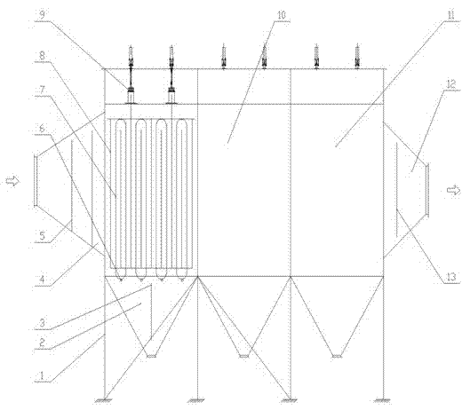
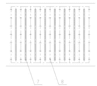
[0027] like figure 1 As shown, the differential mobile horizontal electrode electrostatic precipitator according to the present invention mainly includes a bottom steel frame 1, an ash bucket 2, an ash bucket baffle plate 3, an inlet head 4, an inlet airflow uniform distribution 5, and an anode plate toggle Device 6, anode system 7, cathode system 8, cathode top rapping system 9, casing 10, top cover 11, outlet head 12 and outlet groove plate 13, wherein:

[0028] The bottom steel frame 1 supports the upper shell 10, the two ends of the shell 10 are provided with an inlet head 4 and an outlet head 12, and the lower part is provided with an ash bucket 2, and the ash bucket 2 is equipped with an ash bucket baffle 3, and the inlet head 4 is equipped with an inlet airflow uniform distribution device 5, which can make the flue gas evenly distributed in the box, the a...


PUM


Abstract

The invention relates to a differential movable type transverse electrode electrostatic precipitator which comprises a housing. Two ends of the housing are provided with an inlet seal head and an outlet seal head, the lower part of the housing is provided with an ash bucket, and an anode system and a corresponding cathode system are provided in the housing; the anode system is composed of a plurality of vertically arranged annular anode rows at equal intervals, each anode row annularly moves under the driving of a transmission device, the bottom of each anode row is provided with an anode plate striking gear used for rapping and ash removal, and the cathode system and the anode system form a plurality of evenly-spaced, parallel and alternatively arranged sets of movable type differential electric field perpendicular to the direction of air flow. According to the invention, through cooperation between the movable annular anode rows and the anode plate striking gears at the bottom of the anode rows, the problem of secondary stirring of dust generated by rapping and ash removal of the anode of an electrostatic precipitator is overcome; gaps among anode plates are decreased, migration distance of charged dust is reduced, and an effective dust collecting area of a single electric field is increased.

Description

[0001] technical field [0002] The invention relates to an industrial dedusting device, in particular to an industrial electrostatic precipitator, such as an electrostatic precipitator for purifying industrial kiln tail gas. Background technique [0003] There are mainly two types of high-efficiency dust removal methods recognized by the dust removal industry, one is electrostatic precipitator, and the other is bag filter. The electrostatic precipitator belongs to the multi-stage filter system in the dust removal equipment. It was originally a high-tech product and is the mainstream of the dust removal industry. However, in recent years, electrostatic precipitators in various industries have become the objects required by various environmental protection departments for transformation. There are three main reasons for this: [0004] One is the improvement of national standards, which makes the design standard of the electrostatic precipitator that meets the standard disch...

Claims


Application Information

Patent Timeline
IPC IPC(8): B03C3/10B03C3/76B03C3/47
Inventor 江保祥江森广陆涵军许传胜金林
Owner 江保祥
Why Eureka
Try Eureka