Method for forming semiconductor structure
A semiconductor and stacked structure technology, which is applied in semiconductor/solid-state device manufacturing, electrical components, circuits, etc., can solve problems such as shrinkage, achieve good sidewall morphology, improve efficiency, and reduce etching time
- Summary
- Abstract
- Description
- Claims
- Application Information
AI Technical Summary
Problems solved by technology
Method used
Image
Examples
no. 2 example
[0067] refer to Figure 9 , Figure 9 It is a schematic flowchart of a method for forming a semiconductor structure according to the second embodiment of the present invention, including:
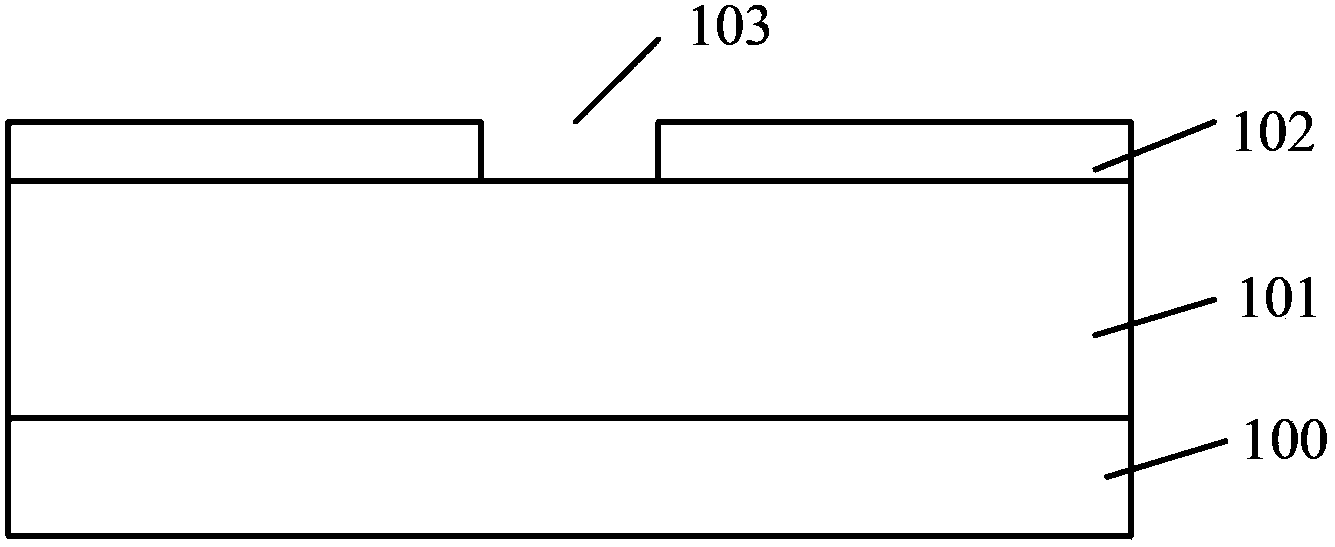
[0068] Step S31, providing a substrate, forming a multi-layer stack structure in which silicon nitride layers and silicon oxide layers are alternately distributed on the substrate, forming a mask layer on the surface of the stack structure, and the mask layer has a surface that exposes the stack structure surface open mouth
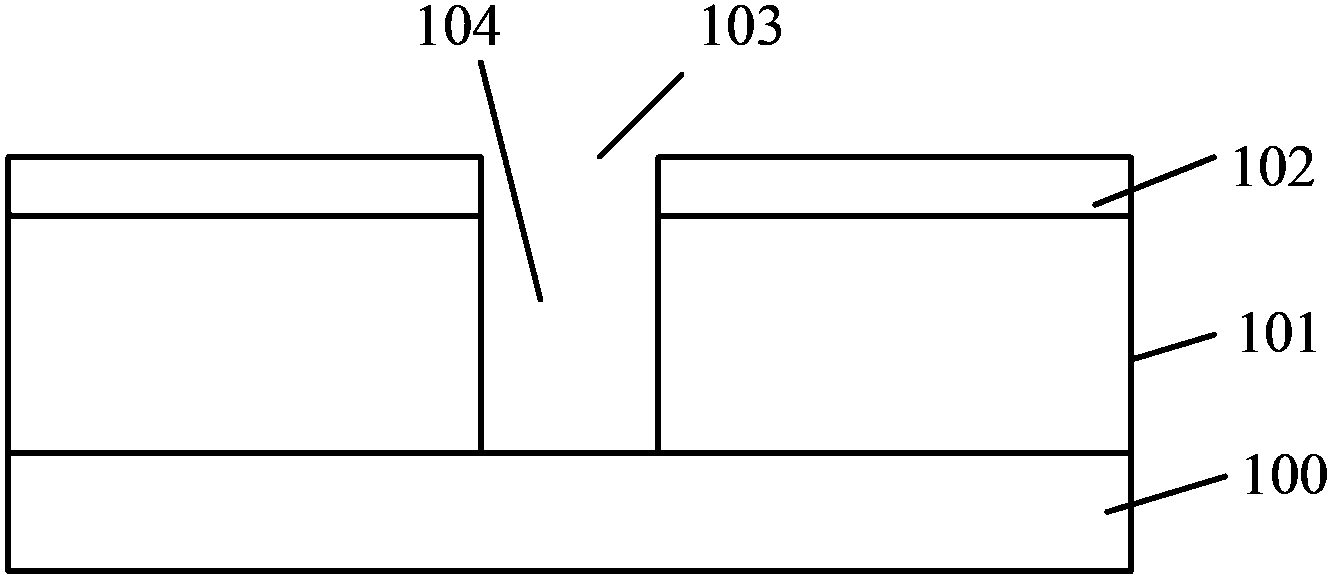
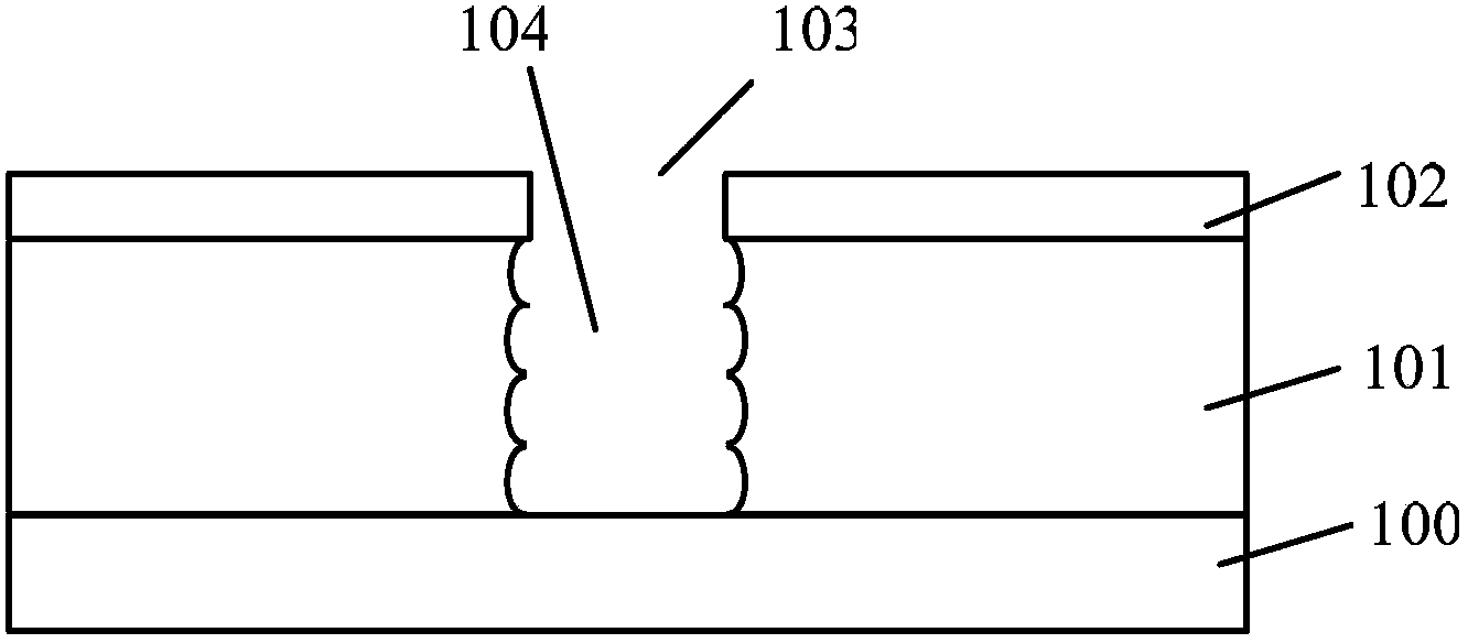
[0069] Step S32, performing plasma etching on the stacked structure, the bias power source outputs bias power in a pulsed manner, the plasma etching is a plasma etching with a continuously decreasing duty cycle, when the bias power When the source is turned on, part of the stacked structure is etched to form an etching hole; when the bias power source is turned off, a polymer is formed on the sidewall and bottom of the formed etching hole, and the bias power source i...
no. 3 example
[0087] refer to Figure 14 , Figure 14 It is a schematic flowchart of a method for forming a semiconductor structure according to the third embodiment of the present invention, including:
[0088] Step S41, providing a substrate, forming a multi-layer stack structure in which silicon nitride layers and silicon oxide layers are alternately distributed on the substrate, forming a mask layer on the surface of the stack structure, and the mask layer has a surface that exposes the stack structure surface open mouth
[0089] Step S42, using plasma with a constant duty ratio to etch the stacked structure to form a first etching hole;
[0090] In step S43 , along the first etching hole, the stack structure is etched with a plasma having a continuously decreasing duty cycle to form a second etching hole, and the first etching hole and the second etching hole form a through hole.
[0091] Figure 15~Figure 17 It is a schematic cross-sectional structure diagram of the formation proc...
no. 4 example
[0110] refer to Figure 18 , Figure 18 It is a schematic flowchart of a method for forming a semiconductor structure according to a fourth embodiment of the present invention, including:
[0111] Step S51, providing a substrate, forming a multi-layer stack structure in which silicon nitride layers and silicon oxide layers are alternately distributed on the substrate, forming a mask layer on the surface of the stack structure, and the mask layer has a surface exposed to the stack structure. open mouth
[0112] Step S52, using a continuous plasma etching process to etch the stacked structure to form a third etching hole;
[0113] Step S53, then performing plasma etching in which the bias power source outputs bias power in a pulsed manner to the stacked structure along the third etching hole to form a fourth etching hole, a third etching hole and a fourth etching hole form a through hole.
[0114] Figure 19~Figure 21 It is a schematic cross-sectional structure diagram of t...
PUM
 Abstract
Description
Claims
Application Information
 - R&D
- Intellectual Property
- Life Sciences
- Materials
- Tech Scout
- Unparalleled Data Quality
- Higher Quality Content
- 60% Fewer Hallucinations
Browse by: Latest US Patents, China's latest patents, Technical Efficacy Thesaurus, Application Domain, Technology Topic, Popular Technical Reports.
© 2025 PatSnap. All rights reserved.Legal|Privacy policy|Modern Slavery Act Transparency Statement|Sitemap|About US| Contact US: help@patsnap.com


