Method for forming crystalline silicon solar cell front electrode
A technology of solar cells and front electrodes, which is applied in the production of printing, circuits, and electrical components of special varieties of printed matter, can solve problems such as increased surface carrier load, and achieve the effects of reducing compounding, saving battery costs, and avoiding direct contact.
- Summary
- Abstract
- Description
- Claims
- Application Information
AI Technical Summary
Problems solved by technology
Method used
Image
Examples
Embodiment 1
[0023] 1) Electrode paste
[0024] Silver paste for printing fine grids for the first time: use ordinary solar cell silver paste with a silver content of 85% and a glass frit softening point of 460°C.
[0025] The second printing of silver paste for busbars: use ordinary solar cell silver paste with a silver content of 80%, glass frit softening point of 500°C, and lower conductivity than silver paste for fine grids.
[0026] 2) Fabrication method of front electrode
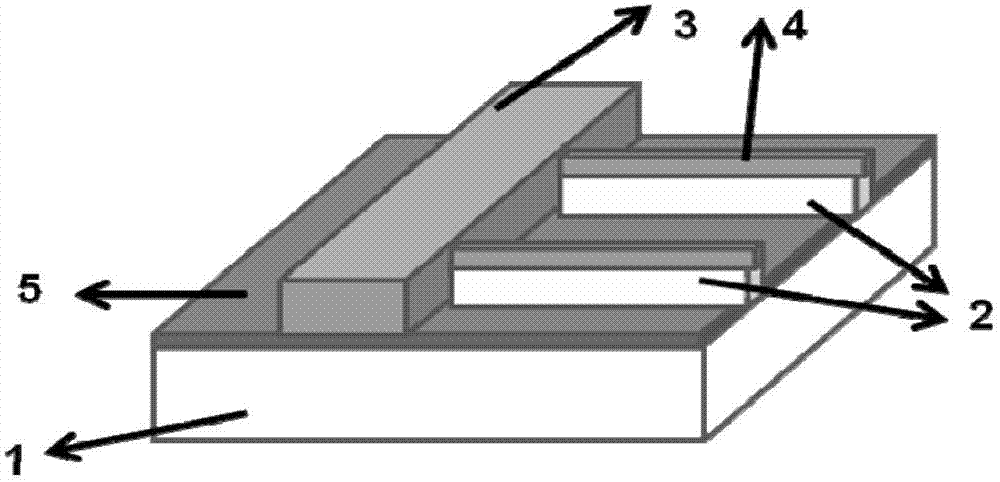
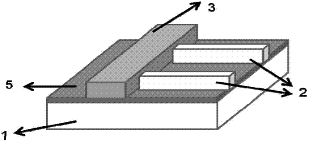
[0027] After texturing, diffusion and surface passivation treatment, anti-reflection film formation on the front, aluminum quilt and back silver electrode are printed on the back of monocrystalline silicon with specifications of 125mmx125mm and textured on both sides, and dried at 200 degrees. First, print a fine-grid silver electrode on the front of the silicon wafer, use the solar cell silver paste described in 1, and dry it in a tunnel furnace at a temperature of 200°C. Then print the main grid in the front e...
Embodiment 2
[0029] 1) Electrode paste
[0030] Silver paste for printing fine grids for the first time: the silver content is 80%, and the softening point of the glass frit is 460°C.
[0031] The second printing of silver paste for busbars: the silver content is 75%, the softening point of glass frit is 500°C, and the conductivity is lower than that of silver paste for fine grids.
[0032] 2) Fabrication method of front electrode
[0033] After texturing, diffusion and surface passivation treatment, anti-reflection film formation on the front, aluminum quilt and back silver electrode are printed on the back of monocrystalline silicon with specifications of 125mmx125mm and textured on both sides, and dried at 200 degrees. First, print a fine-grid silver electrode on the front of the silicon wafer, use the solar cell silver paste described in 1, and dry it in a tunnel furnace at a temperature of 200°C. Then print the main grid in the front electrode and the fine grid for the second time, ...
Embodiment 3
[0035] 1) Electrode paste
[0036] Silver paste for printing fine grids for the first time: the silver content is 80%, and the softening point of the glass frit is 460°C.
[0037] Silver paste for the second printing of busbars: the silver content is 70%, the softening point of the glass frit is 500°C, and the conductivity is lower than that of the silver paste for fine grids.
[0038] 2) Fabrication method of front electrode
[0039] After texturing, diffusion and surface passivation treatment, anti-reflection film formation on the front, aluminum quilt and back silver electrode are printed on the back of monocrystalline silicon with specifications of 125mmx125mm and textured on both sides, and dried at 200 degrees. First, print a fine-grid silver electrode on the front of the silicon wafer, use the solar cell silver paste described in 1, and dry it in a tunnel furnace at a temperature of 200°C. Then print the main grid in the front electrode and the fine grid for the secon...
PUM
| Property | Measurement | Unit |
|---|---|---|
| Softening point | aaaaa | aaaaa |
| Softening point | aaaaa | aaaaa |
Abstract
Description
Claims
Application Information
 - R&D
- Intellectual Property
- Life Sciences
- Materials
- Tech Scout
- Unparalleled Data Quality
- Higher Quality Content
- 60% Fewer Hallucinations
Browse by: Latest US Patents, China's latest patents, Technical Efficacy Thesaurus, Application Domain, Technology Topic, Popular Technical Reports.
© 2025 PatSnap. All rights reserved.Legal|Privacy policy|Modern Slavery Act Transparency Statement|Sitemap|About US| Contact US: help@patsnap.com


