
Draining and oxygen adding device for full-automatic heater

A fully automatic heater technology, applied in chemical instruments and methods, lighting and heating equipment, heat exchange equipment, etc., can solve the problems of unit adjustment performance influence, reporting, and no hydrophobic and oxygen treatment.

Active Publication Date: 2012-10-24
ZHEJIANG ZHENENG TECHN RES INST
View PDF4 Cites 6 Cited by
  • Summary
  • Abstract
  • Description
  • Claims
  • Application Information

AI Technical Summary

Problems solved by technology

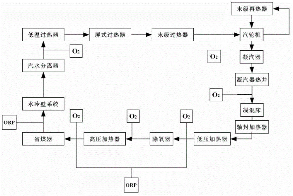
[0005] The specific treatment process of the high-pressure heater drain system leads to flow accelerated corrosion (FAC) of the system, which occurs in a specific water vapor temperature range, high flow rate, and specific chemical conditions (reducing treatment and full volatilization treatment) , at this time, the oxidation-reduction potential (ORP) of the hydrophobic medium is very low (less than 0), and the temperature is between room temperature and 300°C. Water and carbon steel form a loose ferroferric oxide magnetic oxide film through an electrochemical reaction, which cannot Let the metal enter the passivation area to form a dense iron oxide protective film
Flow-accelerated corrosion makes the content of iron in the hydrophobic water high. The solubility of this ferroferric oxide film is the highest at about 150°C-200°C, and it has strong magnetism. It is used in valves and holes of some ferromagnetic materials, such as high-pressure heating Deposition and periodic clogging are formed at the outlets of the #1 high-pressure heater, #2 high-pressure heater and #3 high-pressure heater shell side, desuperheating water regulating valve, sampling valve, etc. The adjustment performance of the
[0006] The current oxygenation treatment is mainly aimed at the oxygenation treatment of feed water, and there is no related report on the oxygenation treatment for hydrophobicity

Method used


Image

  • Draining and oxygen adding device for full-automatic heater
  • Draining and oxygen adding device for full-automatic heater
  • Draining and oxygen adding device for full-automatic heater

Examples


Embodiment Construction

[0056] Taking the existing boiler water vapor circulation system as an example, the fully automatic heater hydrophobic oxygenation device and method of the present invention will be further described:

[0057] Such as figure 2 As shown, the heater of the present invention is three high-pressure heaters whose tube side is connected in series between the water outlet of the deaerator and the water inlet of the economizer; the shell sides of the three high-pressure heaters are also connected in series in sequence, respectively #1 Heaters, #2 High Pressure Heater and #3 High Pressure Heater. There are three stages of pumping at the outlet of the steam turbine to enter the shell side of #1 high-pressure heater, #2 high-pressure heater and #3 high-pressure heater to turn into hydrophobic, and the hydrophobic in the shell side of the high-pressure heater flows into the deaerator step by step, and then It enters the tube side of the high pressure heater through the deaerator. Among...


PUM


Abstract

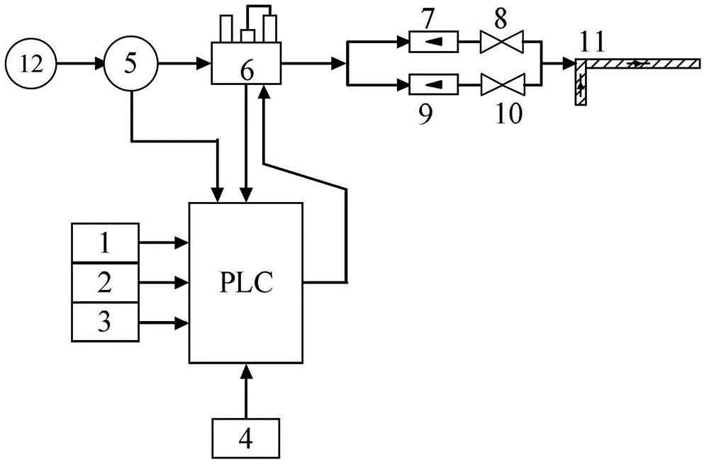
The invention discloses a draining and oxygen adding device for a full-automatic heater. The device comprises the following components: a PLC; a pressure detector for collecting a pressure signal in pipeline at an oxygen adding point, and transmitting the pressure signal to the PLC; a dissolved oxygen content detector for collecting a dissolved oxygen content at a detecting point and transmittingthe dissolved oxygen content signal to the PLC; an oxidation-reduction potential detector for collecting an oxidation-reduction potential at the detecting point and transmitting the oxidation-reduction potential signal to the PLC; a hydrogen conductivity detector for collecting hydrogen conductivity at the detecting point and transmitting the hydrogen conductivity signal to the PLC; and a flow controller connected with an oxygen source and for controlling oxygen addition flow according to the PLC command. The invention also discloses a draining and oxygen adding method for the automatic heater. The oxygen adding device of the invention can avoid clogging of a drainage valve on a high-pressure heater shell side pipeline, and maintain safe and economical operation of the unit at an OT working conditions.

Description

technical field [0001] The invention belongs to the technical field of electric power and power engineering control, and in particular relates to a fully automatic heater hydrophobic oxygenation device and method. Background technique [0002] The structures of the water-steam circulation system of the once-through boiler and the drainage system of the high-pressure heater of the existing super (super) critical thermal power generating unit are as follows: figure 1 and figure 2 shown. [0003] Such as figure 1 As shown, in a once-through boiler, after the feed water of the deaerator is boosted by the feed water pump, it flows sequentially through the high-pressure heater tube side, the economizer, and the water wall system to complete the heating and evaporation of the feed water, and go through three stages of superheating The heating surface such as the boiler becomes superheated steam, which is sent out of the boiler and enters the high-pressure cylinder of the steam ...

Claims


Application Information

Patent Timeline
IPC IPC(8): C02F1/00F28F17/00F28F19/00
Inventor 刘春红施国忠谢尉扬陈统钱缪盛华王宏义
Owner ZHEJIANG ZHENENG TECHN RES INST
Learn More