Reflection-type long grating process method for laser-assisted roll pressing manufacturing machine tool

A laser-assisted and process-based technology, which is applied to the photoplate-making process of the pattern surface, optical mechanical equipment, optics, etc., can solve the problem of limited fluidity of solid metal materials, uncontrollable groove shape of grating scale, and unstable optical path signal And other issues

Inactive Publication Date: 2012-10-31
XI AN JIAOTONG UNIV +1
View PDF4 Cites 9 Cited by
  • Summary
  • Abstract
  • Description
  • Claims
  • Application Information

AI Technical Summary

Problems solved by technology

[0004] Limited to the technical principle that the nanoimprinting process relies on mechanical force to realize the microstructure replica, the traditional roller imprinting technology uses a huge imprinting force to realize the filling of the imprinting material into the microstructure cavity on the mold, thereby completing the microstructure imprinting process. For the replication of structural graphics, especially for the manufacture of reflective grating scales, the imprinting material is metal, which causes it to undergo plastic deformation to fill the cavity of the microstructure on the mold. The imprinting force required is extremely huge, which will cause the imprinting mechanism to The huge deformation of the imprin...

Method used


Image

  • Reflection-type long grating process method for laser-assisted roll pressing manufacturing machine tool
  • Reflection-type long grating process method for laser-assisted roll pressing manufacturing machine tool
  • Reflection-type long grating process method for laser-assisted roll pressing manufacturing machine tool

Examples


Embodiment Construction

[0035] The present invention will be described in detail below through the accompanying drawings and specific implementation examples. But the following implementation examples are only limited to explain the present invention, and the protection scope of the present invention just includes the whole content of claim.

[0036] A specific embodiment of the reflective long grating process method for laser-assisted roll embossing manufacturing machine tool of the present invention is realized through the following steps. The method includes the following steps:

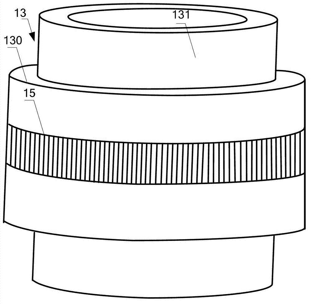
[0037] (1) Quartz roller embossing mold processing: use a single-point diamond tool ultra-precision turning process to process a hollow quartz mold blank to form a roller embossing mold base 13. The shape of the base 13 is as follows Figure 1A As shown, it includes a raised central portion 130 and shoulders 131 on either side of the central portion.

[0038] The roll imprinting mold material used in this embodiment is ...


PUM

PropertyMeasurementUnit
Thicknessaaaaaaaaaa
Thicknessaaaaaaaaaa
Damage thresholdaaaaaaaaaa

Abstract

The invention discloses a reflection-type long grating process method for a laser-assisted roll pressing manufacturing machine tool. The method comprises the following steps that: outgoing beams of excimer laser are modulated into linear beams with uniform light intensity distribution; the linear beams directionally irradiate a pressing region from beginning to end; a metal material on the surface of a grating ruler blank in the pressing region is instantly heated to be at a temperature close to a melting point of the metal material in the instant of pressing, so that the metal material in the region has certain flowability and fills a groove-shaped concave cavity with a grating microstructure on a quartz roll pressing mold under small pressing force; and after a heated region is separated from a laser irradiating region, the metal material is cooled and cured instantly, so that the form of the grating line grain microstructure is maintained, and the high-precision replication of grating line grains from a roll pressing mold to the grating ruler blank is completed. The method disclosed by the invention is suitable for the high-precision and low-cost batch manufacturing of reflection-type long grating (more than one meter) and ultra-long grating (made from a couple of meters of, dozens of meters of and even hundreds of meters of metal belt materials), and has a good promotion value and good application prospect.

Description

technical field [0001] The invention belongs to the technical field of manufacturing long gratings for machine tools, in particular to a laser-assisted roller embossing manufacturing process for reflective long gratings for machine tools. technical background [0002] The grating ruler has the technical advantages of easy installation and high precision, and is suitable for real-time detection of the linear position of the tool and the workpiece during machining. Therefore, the grating ruler has been widely used as a feedback component of the feed system in CNC machine tools. [0003] The current mainstream grating scale manufacturing method is to manufacture a high-precision master grating by photolithography, and then use it as a master for photolithography or mold replication. The process steps are complicated, the accuracy loss is large, and it is difficult to realize due to the limitation of photolithography technology In the manufacture of large-scale and super-long ma...

Claims


Application Information

Patent Timeline
IPC IPC(8): G03F7/00G02B27/09
Inventor 刘红忠史永胜范禅金尹磊冯龙蒋维涛卢秉恒
Owner XI AN JIAOTONG UNIV
Why Eureka
Try Eureka