MEMS (micro-electrochemical systems) accelerometer and production method thereof

A technology of an accelerometer and a manufacturing method, which is applied in the direction of measuring acceleration, velocity/acceleration/shock measurement, and manufacturing microstructure devices, etc., can solve the problem of inability to provide mechanical strength protection structures, insufficient shock resistance of accelerometers, and difficulty in sensitivity of non-sensitive axes. Inhibition and other problems, to achieve the effect of improving yield, low packaging equipment requirements, and small gas damping

Active Publication Date: 2014-04-09
BEIJING MXTRONICS CORP +1
View PDF3 Cites 0 Cited by
  • Summary
  • Abstract
  • Description
  • Claims
  • Application Information

AI Technical Summary

Problems solved by technology

The comb-tooth accelerometer mainly has the following problems: the mechanical strength difference between the sensitive axis and the non-sensitive axis of the sensitive structure is not large, and the sensitivity of the non-sensitive axis of the accelerometer is difficult to suppress; the direction of the sensitive axis cannot provide a protective structure with sufficient mechanical strength , the impact resistance of the accelerometer is insufficient; the output value of the comb-tooth structure capacitance is small, and the sensitivity to external acceleration is low, so the comb-tooth accelerometer is mainly suitable for low-demand environments such as the consumer field
Foreign high-precision MEMS accelerometers adopt the process of cutting the accelerometer wafer into independent small chips, and packaging them in the shell in a vacuum environment. This vacuum packaging method has very strict requirements on the ability of the packaging equipment. The cost of packaging is very high, and it is almost impossible to achieve mass production in China

Method used


Image

  • MEMS (micro-electrochemical systems) accelerometer and production method thereof
  • MEMS (micro-electrochemical systems) accelerometer and production method thereof
  • MEMS (micro-electrochemical systems) accelerometer and production method thereof

Examples


Embodiment Construction

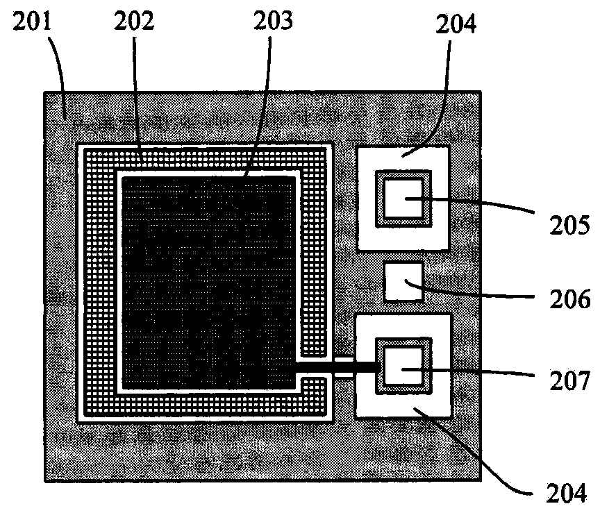
[0039] According to the working principle of capacitance detection, the MEMS high-precision accelerometer adopts a glass-silicon-glass three-layer structure: the metal electrode of the first glass layer forms the first capacitance with the upper surface of the mass block, and the metal electrode of the second glass layer forms the second capacitance with the lower surface of the mass block. Two capacitors; under the action of acceleration perpendicular to the direction of the mass block, the mass block will shift, causing changes in the upper and lower capacitances. Acceleration can be measured by detecting changes in capacitance.

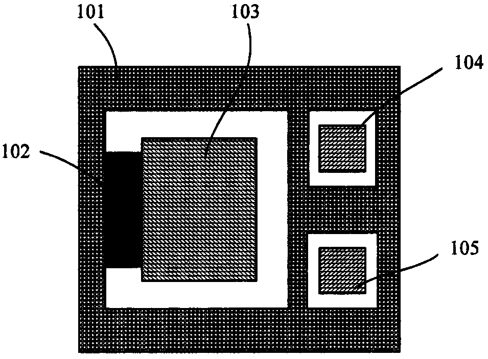
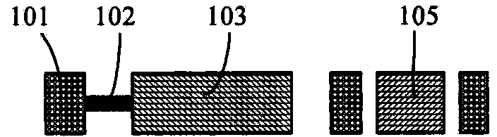
[0040] FIG. 1 is a schematic structural diagram of a silicon layer 1 of a MEMS accelerometer according to the present invention. The silicon layer 1 includes a silicon frame 101 , a proof mass 103 , a support beam 102 , and silicon islands 104 and 105 . The mass block 103 is formed inside the silicon frame 101 , one end of the mass block 103 is con...


PUM

PropertyMeasurementUnit
electrical resistivityaaaaaaaaaa
thicknessaaaaaaaaaa
thicknessaaaaaaaaaa

Abstract

Disclosed are an MEMS (micro-electrochemical systems) accelerometer and a production method thereof. The MEMS accelerometer is in a tri-layer capacitive structure of glass, silicon and glass layers. The silicon layer comprises a first silicon pad and a second silicon pad. The first silicon pad is contacted with a metal electrode of a first glass layer. The second silicon pad is contacted with a metal electrode of a second glass layer. The first glass layer further comprises a first metal electrode outgoing through hole, a second metal electrode outgoing through hole and a silicone layer electrode outgoing through hole, which all form on a first glass substrate. The first metal electrode outgoing through hole corresponds to the first silicon pad in position. The second metal electrode outgoing through hole corresponds to the second silicon pad in position. Metal welding spots form on the first silicon pad and the second silicon pad respectively. A metal welding spot forms at the position on a silicon frame, which corresponds to the silicon layer electrode outgoing through hole. A metal electrode of the glass layer and a silicon layer electrode can be led out in a same plane, and the problem in packaging three electrodes which are led out in different planes is solved.

Description

technical field [0001] The invention relates to a microelectromechanical system (MEMS) device and its manufacturing technology, in particular to a MEMS high-precision accelerometer and its manufacturing method. Background technique [0002] MEMS accelerometers are an indispensable link in MEMS inertial systems and are currently used in many fields. There are two main working principles of MEMS accelerometers: capacitive and piezoresistive. Among them, piezoresistive accelerometers have disadvantages such as low precision and poor temperature characteristics, and their application fields are limited. Capacitive accelerometers mainly adopt two schemes: comb tooth type and "sandwich" type. The comb-tooth accelerometer mainly has the following problems: the mechanical strength difference between the sensitive axis and the non-sensitive axis of the sensitive structure is not large, and the sensitivity of the non-sensitive axis of the accelerometer is difficult to suppress; the d...

Claims


Application Information

Patent Timeline
Patent Type & Authority Patents(China)
IPC IPC(8): G01P15/00B81B3/00B81C1/00
Inventor 张富强杨静孟美玉
Owner BEIJING MXTRONICS CORP
Why Eureka
Try Eureka