Manufacturing method of vacuum external applied load insulation board

A manufacturing method and technology of thermal insulation board, which can be applied to manufacturing tools, ceramic molding machines, etc., can solve the problems of increased operating costs, easy air leakage, increased thermal conductivity, etc. The effect of coefficient reduction

Inactive Publication Date: 2012-11-14
山西华毓恒技术服务有限公司
View PDF3 Cites 2 Cited by
  • Summary
  • Abstract
  • Description
  • Claims
  • Application Information

AI Technical Summary

Problems solved by technology

[0004] Limited by technical conditions, the current vacuum insulation panel manufacturing equipment uses molds to press and shape insulation material particles, put them into vacuum bags, and then enter the vacuum box for vacuum treatment. However, since the insulation material particles have been pressed and formed, This virtually increases the time of vacuuming and increases the operating cost. At the same time, because the insulation forming board is placed horizontally in the vacuum box, the insulation material particles at the opening of the vacuum bag are easily sucked out by the vacuum system during vacuuming. In this way, the sucked out Insulation material particles will not only pollute the vacuum pumping system, but also stick a large number of insulation material particles to the heat-sealed opening of the vacuum bag, resulting in poor heat-sealing effect and easy air leakage of the insulation bag, and the insulation material is uneven after molding. Increased thermal conductivity, wasting energy
[0005] The vacuum insulation panels made by the existing manufacturing equipment, in the process of use, once the vacuum bag is damaged and broken, the vacuum insulation panels in the vacuum bag are very easy to be damp, the vacuum insulation panels will leak, the thermal conductivity will increase greatly, and even the vacuum insulation will appear. Panel collapse accident, shortening the practical life of vacuum insulation panels

Method used


Image

  • Manufacturing method of vacuum external applied load insulation board
  • Manufacturing method of vacuum external applied load insulation board
  • Manufacturing method of vacuum external applied load insulation board

Examples


Embodiment Construction

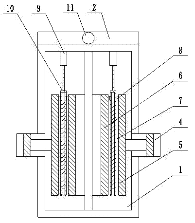
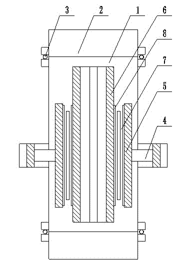
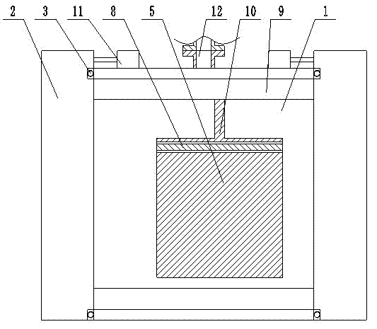
[0040] Such as figure 1 , figure 2 , image 3 As shown, a method for manufacturing a vacuum external load insulation panel of the present invention is carried out according to the following steps:

[0041] The first step is to send the thermal insulation material into the material silo, put the powder forming square box into the PE layer aluminum foil composite film bag, and set a layer of filter material at the opening of the PE layer aluminum foil composite film bag;

[0042] In the second step, use the first clamp to clamp the PE layer aluminum foil composite film bag in the first step except the other three sides of the opening side and transport the clamped PE layer aluminum foil composite film bag to the shaping machine, and then use The template of the shaping machine presses the PE layer aluminum foil composite film bag;

[0043] The third step is to use the spring screw conveyor to measure and output the thermal insulation material from the material silo in the fi...


PUM


Abstract

The invention relates to a manufacturing method of a vacuum external applied load insulation board, belonging to the technical field of vacuum insulation board manufacturing; the manufacturing method in the invention overcomes the disadvantages in the prior art, and provides a manufacturing method of a vacuum external applied load insulation board which is not easy to leak air and cave in, good in planeness, low in coefficient of heat conductivity and short in pumpdown time; in order to solve the technical problem, the technical scheme adopted in the invention comprises the following steps: firstly, loading a thermal insulating material in a PE (Polyethylene) layer aluminum foil composite membrane bag for shaping; secondly, carrying out extrusion forming on the PE layer aluminum foil composite membrane bag in a vacuum box; and finally, taking the formed vacuum insulation board from the vacuum box, and the manufacturing method is mainly used for manufacturing vacuum insulation boards.

Description

technical field [0001] The invention discloses a method for manufacturing a vacuum external load heat insulation board, which belongs to the technical field of vacuum heat insulation board manufacture. Background technique [0002] At present, most of the thermal insulation materials used in the market are organic materials with poor fireproof performance, while the materials used in vacuum insulation panels have good fireproof performance, are Class A non-combustible, and have low thermal conductivity, so vacuum insulation panels are ideal thermal insulation materials. Has a broad market prospect. [0003] Vacuum insulation panel is a thermal insulation material with a thermal conductivity of 0.004W / (m k), and its thickness is thin, generally around 17mm. Under the same thermal conductivity conditions, it is thicker than conventional thermal insulation materials. It is smaller and has a wider range of applications, such as refrigerators, refrigerated containers, medical in...

Claims


Application Information

Patent Timeline
Patent Type & Authority Applications(China)
IPC IPC(8): B28B1/52C04B28/00
Inventor 寇亚明寇博伦陈秀凯李晓森
Owner 山西华毓恒技术服务有限公司
Why Eureka
Try Eureka