
Optical image restoration method based on Kalman filter

A Kalman filter and optical image technology, which is applied in the field of remote sensing image processing, can solve the problems of not considering the aging of the atmosphere and detectors, inaccurate MTF curve measurement, and reduced accuracy of measurement results, so as to improve image quality, be easy to implement, and The effect of simple method

Active Publication Date: 2012-11-14
WUHAN UNIV
View PDF2 Cites 12 Cited by
  • Summary
  • Abstract
  • Description
  • Claims
  • Application Information

AI Technical Summary

Problems solved by technology

In recent years, the MTF measurement method of the imaging system when the satellite is in orbit is mainly to use the knife-edge method or the pulse method to directly extract the imaging data obtained on the orbit, which can solve the problem that the laboratory measurement data does not consider the atmosphere and detector elements. The measurement results are inaccurate due to aging factors, but since the sample data required for measurement are directly obtained from the imaging data, the measurement results will be affected by factors such as satellite platform vibration and noise components in the imaging data. Therefore, the MTF curve obtained by the knife-edge method or the pulse method needs to eliminate the interference frequency components contained in it, otherwise, the restoration result will increase the noise due to the inaccurate frequency measurement value in the MTF
At present, the commonly used method to remove the interference components of the MTF curve is to use the leveling method to directly set the fluctuation components caused by interference on both sides of the line spread function (LSF) to zero or take the average value. Although this method can remove most of the noise component, but it will also eliminate non-interfering components, causing inaccurate measurement of the MTF curve, which further leads to an increase in noise in the restored image

Method used


Image

  • Optical image restoration method based on Kalman filter
  • Optical image restoration method based on Kalman filter
  • Optical image restoration method based on Kalman filter

Examples


Embodiment Construction

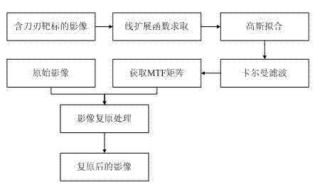
[0024] The technical solution of the present invention can use computer software technology to realize the automatic operation process, and the technical solution of the present invention will be described in detail below in conjunction with the accompanying drawings and embodiments. see figure 1 , the process of the embodiment can be divided into five steps:

[0025] Step 1, extracting the line extension function, including the following sub-steps:

[0026] Step 1.1, perform edge detection to obtain the sub-pixel position of the edge point on each line of the image.

[0027] In the embodiment, the position of the edge is initially estimated, and a simple difference is made to each line of gray value, and the position of the maximum difference point is found to be the position of the edge, and then the values ​​of 4 sample points near the position are used for cubic polynomial curve fitting, assuming The position fit polynomial for the edge found for a row is:

[0028] a(x)...


PUM


Abstract

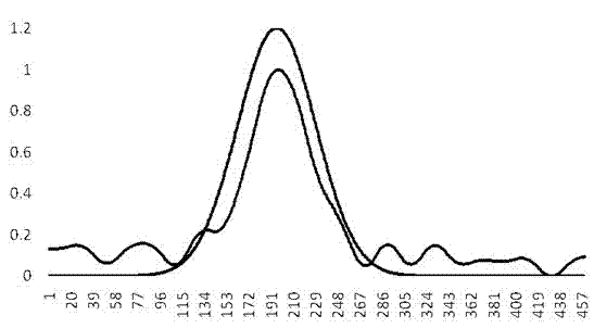
The invention provides an optical image restoration method based on Kalman filter. The method comprises the following steps of 1, extracting a line spread function; 2, Gaussian fitting the line spread function; 3, generating a high precision line spread function based on the Kalman filter; 4, generating an MTF (modulation transfer function) curve and an MTF matrix; and 5, restoring an image by the MTF matrix. Based on an MTF theory and an image quality degradation theory, the method is used for correcting and measuring interference elements in the line spread function by adopting the Gaussian fitting method and Kalman filter method, thereby obtaining a point spread function which is better and more close to the real imaging performance of an imaging system as the basis of image restoration, and improving the image restoration accuracy from the source. The method can be used for effectively restoring images and improving image quality and the algorithm efficiency is high.

Description

technical field [0001] The invention belongs to the field of remote sensing image processing and relates to an optical image restoration method based on Kalman filtering. Background technique [0002] During the operation of the satellite in orbit, due to the influence of factors such as platform flutter and drift angle, the TDI-CCD camera will produce image point displacement in the orbital direction and vertical orbital direction during the integral imaging process, causing image blurring, which seriously affects the image quality. Therefore, it is necessary to restore the image data. Image restoration is based on the imaging model, and an accurate imaging model is the basis of high-precision image restoration. As an important component of the image imaging model, the modulation transfer function (MTF), whose value directly reflects the attenuation of the image at different frequencies, is based on The theory of image quality degradation shows that if the MTF value of the...

Claims


Application Information

Patent Timeline
Patent Type & Authority Applications(China)
IPC IPC(8): G06T5/00G06T7/00
Inventor 王密张炳先李德仁
Owner WUHAN UNIV
Learn More