High-energy gas atomizing nozzle for preparing metal and alloy powder

A technology for alloy powder and high-energy gas is applied in the field of preparing metal and alloy powder high-energy gas atomizing nozzles, which can solve the problems of self-consumption loss of supersonic gas flow, unstable supersonic gas flow, and difficulty in reaching supersonic speed, and achieve high-efficiency fogging. The effect of improving the atomization rate, improving the atomization production efficiency and reducing the loss

Inactive Publication Date: 2012-11-28
ZHEJIANG ASIA GENERAL SOLDERING & BRAZING MATERIAL
View PDF7 Cites 12 Cited by
  • Summary
  • Abstract
  • Description
  • Claims
  • Application Information

AI Technical Summary

Problems solved by technology

For example, the shrinking and expanding nozzle with the non-streamline transition structure of the gas cavity will lose a certain amount of energy when the gas flow flows in the gas cavity, and it also leads to the lack of sufficient acceleration area for the shrinking tube in front of the throat of the shrinking and expanding nozzle. Accelerate the high-pressure gas to the speed of sound, so a higher inlet pressure is required to achieve a supersonic flow from the nozzle of the contracting and expanding nozzle
Otherwise, the air flow will still flow at subsonic speed after passing through the throat of the shrinking and expanding nozzle, and it is difficult to reach supersonic speed
In addition, the contraction-expansion nozzle in the above-mentioned patent has an asymmetric structure, not a Laval contraction-expansion nozzle in the strict sense. Energy self-consumption loss

Method used


Image

  • High-energy gas atomizing nozzle for preparing metal and alloy powder
  • High-energy gas atomizing nozzle for preparing metal and alloy powder
  • High-energy gas atomizing nozzle for preparing metal and alloy powder

Examples


Embodiment 1

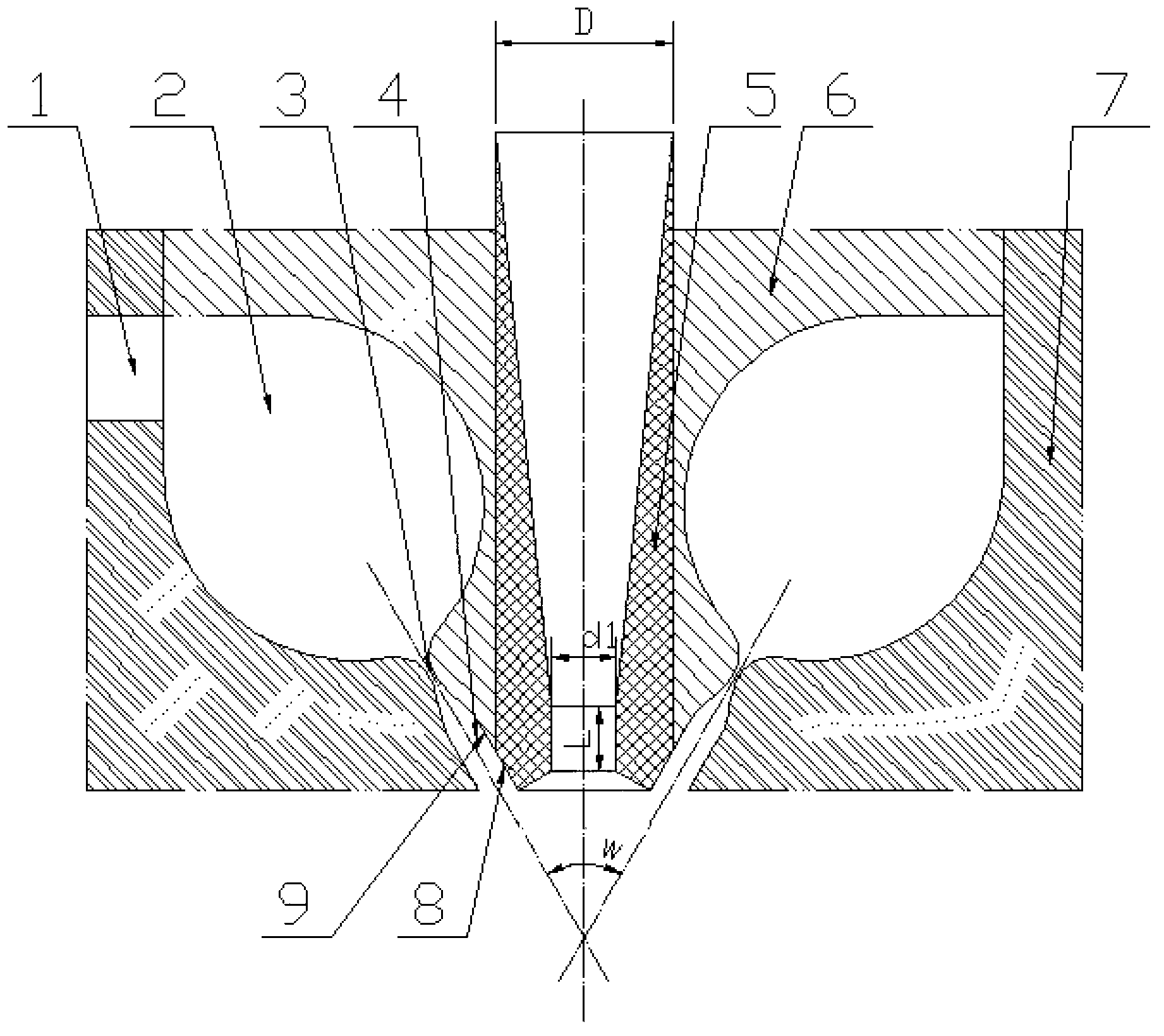
[0020] Such as figure 1 A high-energy gas atomization nozzle for the preparation of metal and alloy powders is shown, including an air inlet pipe 1, a guide pipe 5, an upper end cover 6 and a lower end cover 7, and the upper end cover 6 and the lower end cover 7 form a circle around the guide pipe 5 The surrounding gas cavity 2, the inner side walls of the upper end cover 6 and the lower end cover 7 form a Laval nozzle structure near the bottom end of the draft tube 5. The Laval nozzle structure includes a contraction section, a throat 3 and an expansion section 4. The gas type The cavity 2 has a symmetrical streamlined structure, and the inner surfaces of the gas cavity 2 and the Laval nozzle structure are polished, and the finish of the polished surface reaches grade 11 or above. The lower side wall 8 of the guide tube 5 is tangent to the outlet outer wall 9 of the expansion section 4 . The inside of the guide tube 5 is tapered at the upper end and parallel to the lower end...

Embodiment 2

[0023] Such as figure 1 As shown, the difference from Example 1 is that d1 is 5.0 mm, the outer diameter D of the draft tube is 18 mm, and the length L of the parallel section is 5 mm.

[0024] When working, the standard composition of 17-4PH stainless steel is used for batching 30KG. After the atomization furnace system is evacuated, intermediate frequency induction melting is carried out, and the furnace charge is filled with N after melting. 2 Protection and refining, after the temperature of the furnace rises to 1500°C, the atomization will be carried out. The inlet pressure of the nozzle is 3.5Mpa during atomization, and the atomization gas is high-purity N 2 . The atomization is carried out normally. After atomization, the total weight of the powder in the powder accumulation tank is about 27.9KG. Firstly, the powder is sieved through an 80-mesh sieve, and then sieved through a 500-mesh ultrasonic vibrating sieve to obtain a powder below 500 mesh (that is, 25 μm). Abou...

Embodiment 3

[0026] Such as figure 1 As shown, the difference from Example 1 is that d1 is 4.2 mm, the outer diameter D of the draft tube is 20 mm, and the length L of the parallel section is 5 mm.

[0027] When working, the standard composition of BNi-7 solder is used for batching 30KG. After the atomization furnace system is evacuated, intermediate frequency induction melting is carried out, and the furnace material is melted and then filled with N. 2 Protection and refining, after the temperature of the furnace rises to 1400°C, the atomization is carried out. The nozzle inlet pressure is 3.2Mpa during atomization, and the atomization gas is high-purity N 2 . The atomization is carried out normally. After atomization, the total weight of the powder in the powder accumulation tank is about 28.8KG. Firstly, the powder is sieved through an 80-mesh sieve, and then sieved through a 500-mesh ultrasonic vibrating sieve to obtain a powder below 500 mesh (that is, 25 μm). About 19.0Kg, accounti...


PUM


Abstract

The invention relates to a high-energy gas atomizing nozzle for preparing metal and alloy powder. The conventional atomizing nozzle generates unsteady supersonic gas flow, and is easy to have turbulence phenomenon to cause self-consumption loss of the energy of the supersonic gas flow. The high-energy gas atomizing nozzle comprises an intake pipe, a guide pipe, an upper end cover and a lower end cover, wherein a gas cavity encircled around the guide pipe is formed between the upper end cover and the lower end cover, inner sidewalls of the upper end cover and the lower end cover form an Laval spray pipe structure near the bottom end of the guide pipe, the Laval spray pipe structure comprises a contraction section, a throat and an expansion section, the high-energy gas atomizing nozzle is characterized in that the gas cavity is a symmetrical streamline structure, and the lower sidewall of the guide pipe is tangential to the outer wall of an outlet of the expansion section. According to the invention, through the Laval contraction-expansion type spray pipe in the symmetrical structure, the turbulence between the accelerated airflow can be reduced, the steady high-energy supersonic gas stream is generated, the efficient atomizing rate of the metal and the alloy thereof can be realized, and superfine powder of lower than 500 meshes reaches more than 65% in the prepared metal powder.

Description

technical field [0001] The invention relates to a device for producing superfine powder by atomizing molten metal with high-energy gas, in particular to a high-energy gas atomizing nozzle for preparing metal and alloy powder. Background technique [0002] Gas atomization to prepare metal and alloy powders has low harmful gas content and good powder sphericity, and is currently one of the most common powder preparation methods. The free-falling molten metal is usually atomized using unrestricted gas atomizing nozzles. The nozzle structure of this atomization method is simple, easy to control, and the liquid metal leak is not easy to block, so the production cost is low, but the average particle size of the obtained powder is relatively coarse, and the proportion of fine powder is low, generally distributed in the range of 60-300μm. In order to improve the gas atomization efficiency, a restrictive structure atomization nozzle was later developed, which shortened the gas fligh...

Claims


Application Information

Patent Timeline
Patent Type & Authority Applications(China)
IPC IPC(8): B22F9/08
Inventor 龙郑易金霞赵文军张腾辉
Owner ZHEJIANG ASIA GENERAL SOLDERING & BRAZING MATERIAL
Why Eureka
Try Eureka