System and method for distributed optical fibre sensing measurement based on Brillouin scattering
A technology of Brillouin scattering and distributed optical fiber, which is applied in the direction of measuring devices, instruments, etc., can solve the problems of limiting the practicality of BOTDR, high cost, and low measurement accuracy
- Summary
- Abstract
- Description
- Claims
- Application Information
AI Technical Summary
Problems solved by technology
Method used
Image
Examples
Embodiment 1
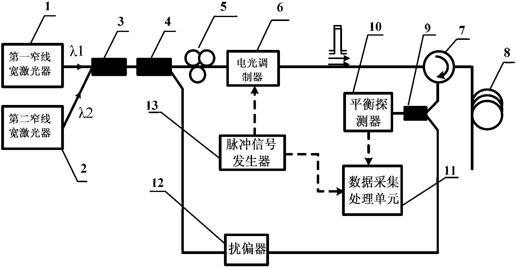
[0036] In this example, the structure of the distributed optical fiber sensing measurement system based on Brillouin scattering is as follows: figure 1 As shown, the solid connection lines between the components in the figure indicate the optical path, and the dotted connection lines indicate the circuit. The first narrow linewidth laser 1 and the second narrow linewidth laser 2 are distributed feedback semiconductor lasers with a linewidth of about 1 MHz, and the output wavelengths of the first narrow linewidth laser 1 and the second narrow linewidth laser 2 are λ1 and λ2 respectively The continuous laser, the wavelength difference between λ1 and λ2 is 20nm. The continuous laser λ1 and λ2 are connected to the multiplexer 3 and enter the coupler 4 to be divided into two paths, one path is used as the probe light, and the other path is used as the local oscillator light; the probe light containing λ1 and λ2 first enters the polarization controller 5, and then accesses the pulse...
Embodiment 2
[0048] In this example, the structure of the distributed optical fiber sensing measurement system based on Brillouin scattering is as follows: Figure 4 As shown, the detection optical path is similar to that of Embodiment 1, but an erbium-doped fiber amplifier 14 is connected between the electro-optic modulator 6 and the circulator 7 . The erbium-doped fiber amplifier 14 amplifies the peak power of the optical pulse to be close to the Brillouin threshold of the sensing fiber 8, so as to obtain the maximum sensing distance.
[0049] The local oscillator light from the coupler 4 is first passed through the local oscillator polarization controller 18 and then connected to the local oscillator electro-optic modulator 16, and the microwave signal source 17 is connected to the local oscillator electro-optic modulator 16; the local oscillator optical pulse output by the local oscillator electro-optic modulator 16 The 3dB optical coupler 9 is connected through the polarization scramb...
PUM
| Property | Measurement | Unit |
|---|---|---|
| Extinction ratio | aaaaa | aaaaa |
Abstract
Description
Claims
Application Information
 - R&D
- Intellectual Property
- Life Sciences
- Materials
- Tech Scout
- Unparalleled Data Quality
- Higher Quality Content
- 60% Fewer Hallucinations
Browse by: Latest US Patents, China's latest patents, Technical Efficacy Thesaurus, Application Domain, Technology Topic, Popular Technical Reports.
© 2025 PatSnap. All rights reserved.Legal|Privacy policy|Modern Slavery Act Transparency Statement|Sitemap|About US| Contact US: help@patsnap.com


