Direct-current attenuation variable-frequency demagnetizing device

A technology of DC attenuation and degaussing device, which is applied in the direction of magnetic objects, magnetic performance measurement, electrical components, etc., can solve problems such as damage to electrical equipment in the power grid, frequent failure of transformer operation, and power failure of transformers, so as to ensure safe and normal operation and improve national quality. Economic benefit, fast degaussing time effect

Active Publication Date: 2012-11-28
XIAN XU&HUI ELECTROMECHANICAL TECH CO LTD
View PDF8 Cites 15 Cited by
  • Summary
  • Abstract
  • Description
  • Claims
  • Application Information

AI Technical Summary

Problems solved by technology

[0003] 1. Causes the relay protection device of the transformer to malfunction, causing frequent failures in the operation of the transformer;
[0004] 2. The voltage surge generated when the short-circuit fault of the transformer outgoing line is removed, which induces the malfunction of the transformer protection and causes all the loads on each side of the transformer to be cut off;
[0005] 3. The excitation inrush current generated by a transformer in A power station connected to the power supply without load induces the "sympathetic inrush" (sympathetic inrush) of the operating transformers in other neighboring power stations B and C, which cause a large-scale power outage;
[0006] 4. The excitation inrush current with a large value will cause damage to the transformer and circuit breaker due to excessive electromotive force;
[0007] 5. Induce control overvoltage and damage electrical equipment in the power grid;
[0008] 6. The DC component in the excitation inrush current causes the magnetic circuit of the current transformer to be over-magnetized, which greatly reduces the measurement accuracy and the correct action rate of the relay protection device;
However, the AC degaussing equipment is only suitable for transformer and transformer manufacturers to use in the laboratory, because it is huge and heavy, it is not suitable for field application, the composition is complicated, and the operation is cumbersome.

Method used


Image

  • Direct-current attenuation variable-frequency demagnetizing device
  • Direct-current attenuation variable-frequency demagnetizing device
  • Direct-current attenuation variable-frequency demagnetizing device

Examples


Embodiment 1

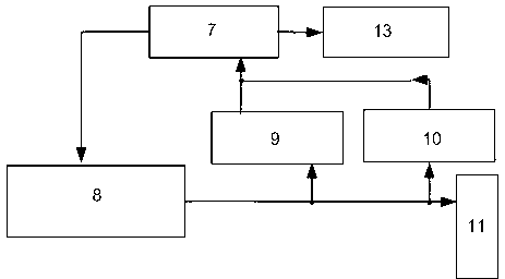
[0032] Embodiment 1: as figure 1 As shown, a DC attenuation frequency conversion degaussing device includes a DC attenuation frequency conversion source 8, a control acquisition unit 7, an attenuation frequency conversion signal current detection unit 9, an attenuation frequency conversion signal voltage detection unit 10, and a degaussing output unit 11. The output end of the DC attenuation frequency conversion source 8 is connected to the input end of the degaussing output unit 11, and the output end of the degaussing output unit 11 is connected to the high voltage end of the electrical equipment to be degaussed; the DC attenuation frequency conversion source 8 is used to output The DC attenuation and frequency conversion degaussing signal is connected to the degaussed test product after the overcurrent and overvoltage protection of the DC attenuation and frequency conversion signal through the degaussing output unit 11; the attenuation and frequency conversion signal current...

Embodiment 2

[0038] Embodiment 2: as Figure 5 As shown, the DC attenuation and frequency conversion degaussing device of the present invention includes not only all the components in Embodiment 1, but also an AC signal source 2 , an AC current detection unit 3 , an AC voltage detection unit 4 , and a measurement output unit 5 .

[0039] The AC signal source 2 is controlled by the control acquisition unit 7, and is used to generate an AC measurement signal to provide a signal source for the residual magnetism measurement of the electrical equipment to be degaussed, and the AC measurement signal output by the AC signal source 2 passes through the measurement output unit 5 applied to the low voltage side of the electrical equipment.

[0040]The AC current detection unit 3 and the AC voltage detection unit 4 are respectively used to detect the AC current signal and the AC voltage signal in the AC measurement signal, and input the detected AC current signal and AC voltage signal to the control...

Embodiment 3

[0044] Embodiment 3: as attached Figure 6 As shown, in addition to the circuit structure described in Embodiment 2, the DC attenuation and frequency conversion degaussing device of the present invention further includes a power conversion unit 1 , a man-machine dialogue unit 6 , a display unit 12 and a test report output unit 14 .

[0045] The power conversion unit 1 mainly converts AC220V into various power supplies required by each unit to ensure the normal operation of other active units; such as: +5V DC power supply control acquisition unit 7 and expert analysis system 13; +12V DC power supply Supply display unit 12 and test report output 14; ±15V DC power supply to detection units 3, 4, 9, 10; ±96V DC power supply to DC attenuation variable frequency source 8; 400V AC power supply to AC signal source 2.

[0046] The man-machine dialogue unit 6 is mainly an operation unit for people to set parameters, input data and confirm commands of the device of the present invention....


PUM


Abstract

The invention provides a device which is used for eliminating and measuring residual magnet of a large-capacity high-voltage large-sensing electrical device of an electric power system. An innovative direct-current attenuation variable-frequency technology is adopted to produce a direct-current attenuation variable-frequency signal to demagnetize a high-voltage end of a mutual inductor and a power transformer; and simultaneously an alternative-current signal is applied to a low-voltage end of the mutual inductor and the power transformer to measure the residual magnet through a particular method. The direct-current attenuation variable-frequency demagnetizing device achieves a small size, a light weight, thorough demagnetization, rapidness in demagnetization, simpleness in measurement of residual magnet and the like. The weaknesses of an alternative-current method such as large size, heavy weight, inconvenience for on-site application, complicated structure and complexity in operation can be overcome, the effect of the alternative-current method is achieved, and the residual magnet is quantitatively measured. The safe and normal running of the power equipment can be guaranteed, and the national economic benefit can be further improved.

Description

technical field [0001] The invention belongs to the technical field of electric power system inductive equipment, and relates to a large-capacity, high-voltage, high-inductance electrical equipment for the elimination of residual magnetism and the measurement of residual magnetism, in particular to a kind of residual magnetism after measuring the DC resistance of a power transformer and transformer Elimination and measurement of residual magnetism. Background technique [0002] Due to the inherent hysteresis of ferromagnetic materials, residual magnetism will remain in the iron core after performing voltage ratio and DC resistance measurements on power transformer transformers. Due to the existence of residual magnetism, when the transformer is put into operation, the residual magnetism of the core will saturate the transformer core for half a cycle, resulting in a large amount of excitation current, and the excitation current will carry a large number of harmonics. This no...

Claims


Application Information

Patent Timeline
Patent Type & Authority Applications(China)
IPC IPC(8): H01F13/00G01R33/12
Inventor 张振存铁大林张忠元潘剑南梁汉城付克勤韩彦华莫文华
Owner XIAN XU&HUI ELECTROMECHANICAL TECH CO LTD
Why Eureka
Try Eureka