Antenna and multiple input multiple output (MIMO) antenna with same

An antenna and feeder technology, applied in the field of MIMO antennas, can solve the problems of versatility and performance differences, antenna performance differences in design and use, and achieve strong anti-interference ability, low operating frequency, and small volume.

Inactive Publication Date: 2012-11-28
KUANG CHI INNOVATIVE TECH
View PDF2 Cites 4 Cited by
  • Summary
  • Abstract
  • Description
  • Claims
  • Application Information

AI Technical Summary

Problems solved by technology

[0004] At the same time, there are large differences in the working environment and electromagnetic characteristics of antennas in different products, which will lead to large differences in antenna perfo

Method used


Image

  • Antenna and multiple input multiple output (MIMO) antenna with same
  • Antenna and multiple input multiple output (MIMO) antenna with same
  • Antenna and multiple input multiple output (MIMO) antenna with same

Examples


Embodiment 2

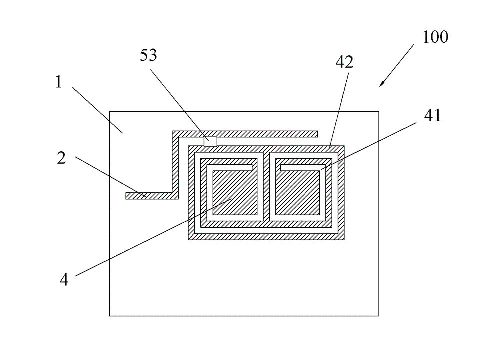
[0042] Such as image 3 As shown, in this embodiment, a space 53 for embedding capacitive electronic components is preset between the feeder 2 and the metal sheet 4, and the preset position for embedding the electronic component space may be between the feeder 2 and the metal sheet 4 any position. image 3 The middle space 53 is the space for embedding capacitive electronic components in this embodiment. There is a certain capacitance between the feeder 2 and the metal sheet 4. Here, the signal coupling between the feeder line and the metal sheet 4 is adjusted by embedding capacitive electronic components. formula: It can be seen that the capacitance value is inversely proportional to the square of the operating frequency, so when the required operating frequency is a lower operating frequency, it can be realized by embedding appropriate capacitors or inductive electronic components. In this embodiment, the capacitance value range of the added capacitive electronic componen...

Embodiment 3

[0044] Such as Figure 4 As shown, in this embodiment, a space for embedding inductive electronic components and / or resistors is reserved on the metal wiring 42 of the metal sheet, and the space for embedding electronic components is not limited to the space 55 and the space given in the figure 56. Other positions are acceptable as long as the conditions are met. The purpose of embedding inductive electronic components here is to increase the inductance value of the resonant structure inside the metal sheet, thereby adjusting the resonant frequency and working bandwidth of the antenna; same as the first embodiment, the purpose of embedding resistors here is to improve the antenna's radiation resistance. As for embedding inductive electronic components or resistors, it depends on the needs. In addition, wires are used to short-circuit in the space where electronic components are not embedded.

Embodiment 4

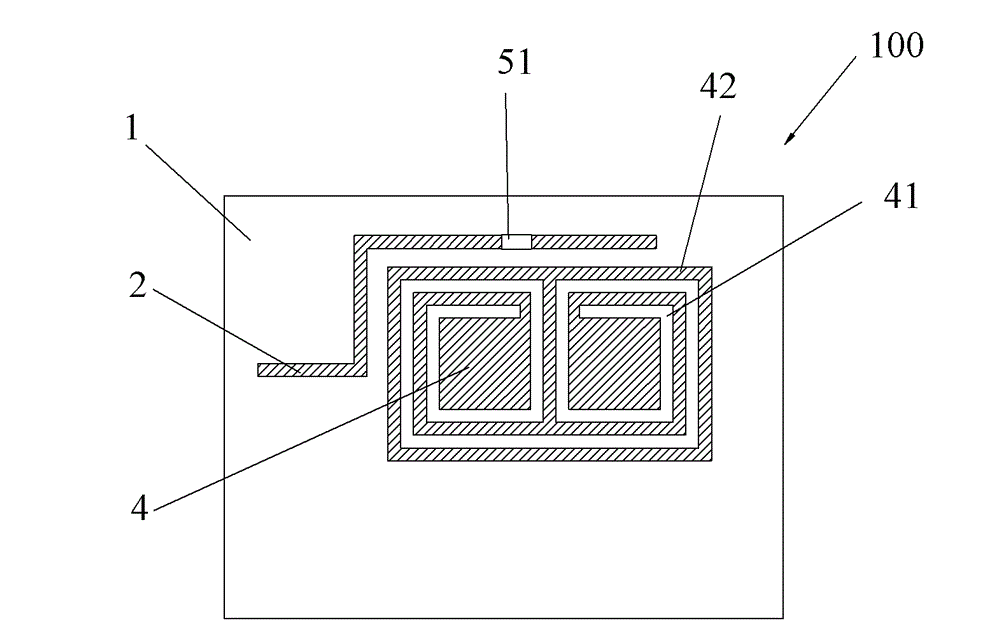
[0046] Such as Figure 5 As shown, in this embodiment, a space for embedding capacitive electronic components is reserved on the microgroove structure 41 , and the space connects the metal wires 42 on both sides of the microgroove structure 41 . The space for embedding electronic components is not limited only to the Figure 5 The space 57 given in , other locations are all available as long as the conditions are met. Embedding capacitive electronic components can change the resonance performance of the metal sheet, and ultimately improve the Q value and resonance operating point of the antenna. As common knowledge, we know that the relationship between the passband BW, the resonant frequency w0 and the quality factor Q is: BW=wo / Q, this formula shows that the larger Q is, the narrower the passband is, and the smaller Q is, the wider the passband is. In addition: Q=wL / R=1 / wRC, wherein, Q is the quality factor; w is the power frequency when the circuit resonates; L is the ind...


PUM

PropertyMeasurementUnit
Inductance valueaaaaaaaaaa
Capacitanceaaaaaaaaaa

Abstract

The invention relates to an antenna, which comprises a first dielectric substrate, a feeder line, a metal sheet and a second dielectric substrate, wherein the metal sheet is attached to one surface of the first dielectric substrate; the second dielectric substrate covers the metal sheet; the feeder line feeds a signal in the metal sheet in a coupling way; a micro-channel structure is hollowed in the metal sheet to form metal wiring on the metal sheet; and spaces are formed in advance in the antenna, and electronic components are embedded into the spaces. According to the antenna, electromagnetic waves are received or transmitted through the second dielectric substrate, so that the overall distributed capacitance of the antenna is improved to effectively lower the working frequency of the antenna, the antenna can work well at low frequency under the condition of no changes in the length of the feeder line, and the requirements of small size, low working frequency and broadband multimode for the antenna are met. In addition, the invention also relates to a multiple input multiple output (MIMO) antenna with a plurality of antennae.

Description

technical field [0001] The invention belongs to the communication field, and in particular relates to an antenna and a MIMO antenna with the antenna. Background technique [0002] With the high development of semiconductor technology, higher and higher requirements are put forward for the integration of today's electronic systems, and the miniaturization of devices has become a technical issue of great concern to the entire industry. However, unlike the development of IC chips following "Moore's Law", radio frequency modules, another important component of electronic systems, face the difficult technical challenge of device miniaturization. The radio frequency module mainly includes main components such as frequency mixing, power amplifier, filter, radio frequency signal transmission, matching network and antenna. Among them, the antenna is the radiating unit and receiving device of the final radio frequency signal, and its working characteristics will directly affect the w...

Claims


Application Information

Patent Timeline
IPC IPC(8): H01Q1/38H01Q21/00
Inventor 刘若鹏徐冠雄杨松涛
Owner KUANG CHI INNOVATIVE TECH
Why Eureka
Try Eureka