Electron bombardment type evaporation source system

A technology of electron bombardment and evaporation source, applied in the field of electron bombardment evaporation source system, can solve problems such as affecting the quality of the film layer, and achieve the effects of high degree of automation, interference prevention and simple structure

Inactive Publication Date: 2012-12-05
DONGGUAN ANWELL DIGITAL MASCH CO LTD
View PDF6 Cites 6 Cited by
  • Summary
  • Abstract
  • Description
  • Claims
  • Application Information

AI Technical Summary

Problems solved by technology

In the production process of OLED, the electron beam heating source is commonly used, which is mainly composed of a hot cathode for providing electrons, an accelerating electrode for accelerating electrons, and an anode. The electrons emitted by the hot cathode are deflected under the action of electric field and magnetic field. The evaporation material is bombarded to evaporate, and the evaporated material is then evaporated onto the glass substrate; the electron beam heating source is characterized by high energy concentration, which can make the local surface of the film obtain extremely high temperature (up to 3000-6000 ℃, Energy density is 10 4 ~10 9 W / cm 2 ), through the adjustment of electrical parameters, the temperature can be accurately controlled and the adjustable temperature range is large, and there is no need to directly heat the crucible, and it can be cooled by water, which avoids the pollution of the crucible material to the film layer; but in the electron beam evaporation source In the process, most compound materials will emit many harmful discrete electrons when they are bombarded by electrons, and the residual gas molecules and membrane material vapor will be partially ionized by electrons, which will affect the quality of the membrane layer.

Method used


Image

  • Electron bombardment type evaporation source system
  • Electron bombardment type evaporation source system
  • Electron bombardment type evaporation source system

Examples


Embodiment Construction

[0020] Embodiments of the present invention will now be described with reference to the drawings, in which like reference numerals represent like elements.

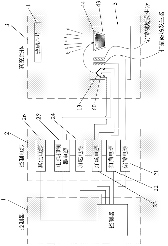
[0021] Such as figure 1 As shown, the electron bombardment evaporation source system provided by the present invention includes a controller 1 , a control power supply 2 and a vacuum chamber 3 . Wherein, the control power supply 2 includes a deflection power supply 21, a scanning power supply 22, a filament power supply 23, an acceleration power supply 24, an arc suppressor power supply 25 and other power supplies 26, and the above-mentioned power supplies are electrically connected to the controller 1 respectively; The coated glass substrate 4 is input and the glass substrate 4 is coated therein. An electron bombardment evaporation source 5 is arranged at a position below the glass substrate 4 in the vacuum chamber 3; Crucible 43, filament 13, arc suppressor 60, scanning magnetic field generator and deflection magnetic ...


PUM


Abstract

The invention discloses an electron bombardment type evaporation source system which comprises a crucible mechanism, an electron beam generation mechanism, a scattered electron absorption pole and an ion collector. The crucible mechanism is provided with a plurality of crucibles, the scattered electron absorption pole is arranged above the crucibles, an outlet hole corresponding to the crucibles is arranged at the upper end of the electron beam generation mechanism, and the ion collector is positioned above the electron beam generation mechanism. Electron beams generated by the electron beam generation mechanism deflect by 270 degrees under the action of an electric field and a deflecting magnetic field to be incident into the crucibles so as to form an e-shaped track, and interference of scattered electrons can be effectively prevented. The scattered electron absorption pole is used for absorbing stimulated harmful scattered electrons, and the ion collector is used for absorbing ionized positive ions, so that a film layer and a substrate are effectively protected. The electron bombardment type evaporation source system is long in feeding period and beneficial to large-scale production by the aid of the crucibles, and is simple in structure, simple and convenient to operate and high in automation degree.

Description

technical field [0001] The invention relates to the technical field of evaporation coating, in particular to an electron bombardment evaporation source system of a coating machine used for coating organic light-emitting diodes and solar panels. Background technique [0002] In the production process of Organic Light-Emitting Diode (OLED) and solar panels, many structural layers are formed by vacuum coating process. Therefore, the quality of vacuum coating directly affects the product quality of OLEDs and solar panels. , the following is an introduction with OLED as the background: [0003] Vacuum coating technology is an indispensable technology for the formation of many OLED film layers, especially vacuum evaporation coating technology. The so-called vacuum evaporation coating means that in the vacuum chamber, the evaporating substances such as metals and compounds are placed in the crucible or hung on the hot wire as the evaporation source, and the workpieces to be plated...

Claims


Application Information

Patent Timeline
IPC IPC(8): C23C14/30
Inventor 叶宗锋刘惠森杨明生
Owner DONGGUAN ANWELL DIGITAL MASCH CO LTD
Why Eureka
Try Eureka